Jump to content


Photo

BG5A - Another GT that needs some TLC


  • Please log in to reply
120 replies to this topic

#1 Ordex

Ordex

    New Member

  • Members
  • Pip
  • 93 posts
  • Gender:Male
  • Location:Hobart

Posted 26 April 2016 - 11:12 AM

Hi all,

Signed up here because I recently bought a Legacy GT, according to the VIN and compliance plate it is a BG5A with an EJ20H and I was told it's a 1993 edition (based on the rego and stamp on the oil cap - lol). It came to Australia under the dodgy VicRoads rebirth scheme as it has a 6T9REPV vin, so that casts some doubt in my mind as to the claims of the compliance plates, oil cap, etc.


The car has boost issues and I was given a big box of spare parts by the previous owner (including a BBOD, exhaust actuator, etc.) and clearly someone has tried to swap this and that to sort the issue. I have done plenty of forum searching and googling. Looking at diagrams on the net I can see they haven't followed any of them.


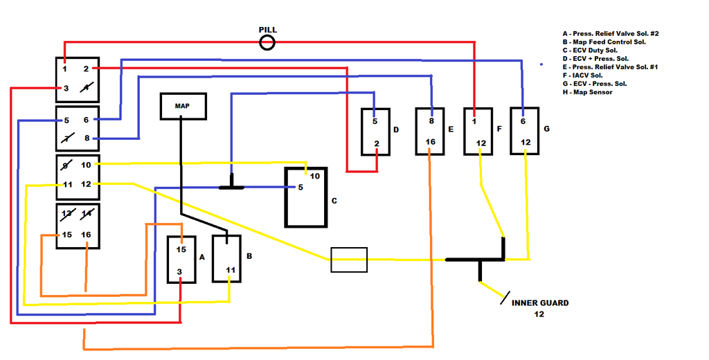
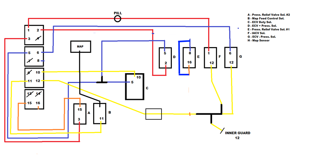
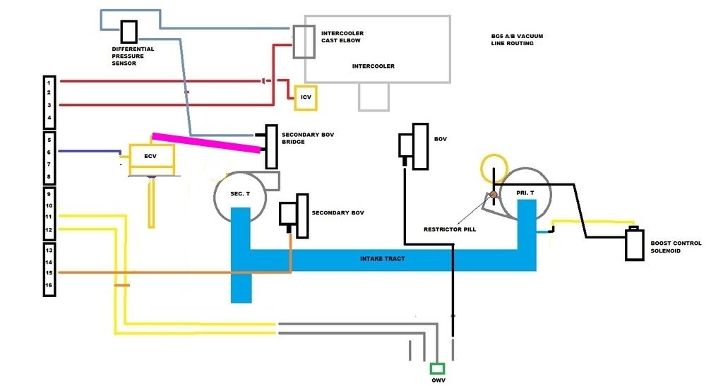
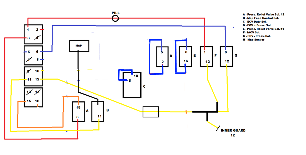
After taking out the BBOD to inspect it I noticed it has 10 lines connected, according to this post a 1993 BG5A should have 11 lines!?


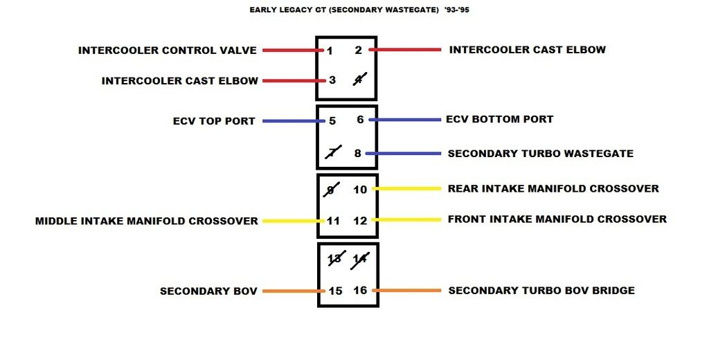
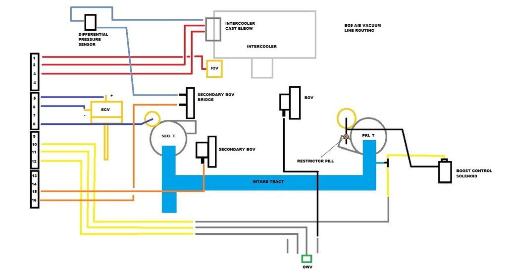
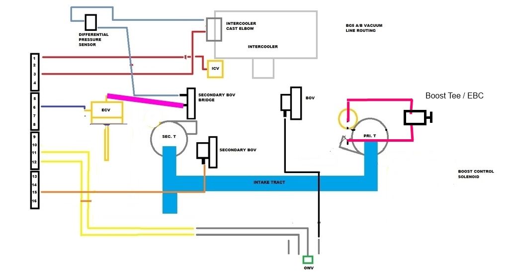
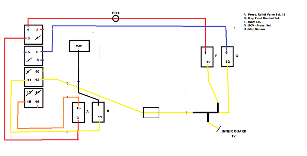
In this diagram of the system with 11 lines I have quickly realised the 11th line I'm missing is the one going to the secondary turbo wastegate. The reason is there is no wastegate on the secondary turbo!


It was a bit hard to read the turbo numbers without taking too much off the car, but as far as I can tell I have a VF18 primary and VF19 secondary (obviously with no wastegate). The numbers certainly don't look like a 13 or 14, which I was expecting.

The ECU is a 7C Mines edition - am I correct to think this is an aftermarket tuned up EJ20H ECU?


Before I can go any further I need some help to work out:

  • How can I tell what the engine in the car actually is (eg. was it swapped at some point).
  • What engine did the VF18/19 turbos come on? Has someone "upgraded" to them?
  • Will a 7C ecu even work with a VF18/19 combo?
  • Which set of BBOD/vac line diagrams should I be following for this setup?

Any help is appreciated, I've attached pics of plates and numbers I've found so far, as well as a diagram of the existing BBOD plumbing.

Attached Files


#2 motoboy76

motoboy76

    Regular Member

  • Members
  • PipPipPip
  • 689 posts
  • Gender:Male
  • Location:Newy.....
  • Interests:Subaru's, Dirt and road bikes......

Posted 26 April 2016 - 06:00 PM

Head to the tt thread might help to....

There are some top blokes around here that should be able to help...

#3 Jimbo

Jimbo

    Livin' the Legacy

  • Members
  • PipPipPip
  • 2,771 posts
  • Gender:Male
  • Location:B'town

Posted 26 April 2016 - 06:38 PM

With the information given, it's likely around a '94 or '95 GT with a manual transmission.

It's not supposed to have the VF18/19 combo as the later GT facelift ('96 to late '97) revised some of the TT system. From memory, the facelift version had only a 3 plug ECU, so this ECU will work with your car as a quick search found the 7C ECU is the standard ECU.

It sounds like someone might have put a GTB engine into the car. If you can, have a look at the injectors and see if they're yellow. Another giveaway is the orange sticker on the AFM.


I'm not really sure what you have to do to the early revision setup to delete the secondary wastegate. The Mines ECU will be tuned to account for it so it might freak out without the secondary wastegate there. I think you really need a pre-facelift solenoid box (11 lines) and the matching turbos (VF13/14). You can't just plonk in a GTB ECU as the wiring is different too.

Confirm the few details I tasked you to get and we can go from there.

Better yet, take a clear photo of the engine bay from top down and another near the fuel rails. This will help immensely.


'04 Liberty GT Premium "The Sprog Chariot"


#4 Ordex

Ordex

    New Member

  • Members
  • Pip
  • 93 posts
  • Gender:Male
  • Location:Hobart

Posted 26 April 2016 - 07:48 PM

Thanks for the help guys.


Injectors look grey to me and all three AFMs (one on the car and two in the box of bits) don't have any orange stickers.


Took all photos as requested, happy to take more if it will make things easier. Obviously the BBOD is not in the engine bay shot.


Of the two BBODs the left one is out of the car and the right is the spare. Left one has the correct numbering externally for an 11 line box. I think I have everything to piece together whatever is required between the two of them so long as I have a good diagram to follow.


I read the engine model can be found somewhere at the back under the intercooler? Does this sound right? If so I'll try pull it off over the next few days to check.

Attached Files


#5 Jimbo

Jimbo

    Livin' the Legacy

  • Members
  • PipPipPip
  • 2,771 posts
  • Gender:Male
  • Location:B'town

Posted 26 April 2016 - 08:25 PM

Okay.

Looks like it's the original engine so that's a good place to start. Someone might have replaced the turbos, thinking it would solve the problem. As I said, unless there's a way to by-pass the original secondary wastegate setup, the best you can do is find the correct secondary turbo for it (VF14).

You are then presented with the task of re-routing all the vacuum hoses! Bitch of a job especially when reference material is very limited on early TT's. I can't find a diagram anywhere (so far) as most diagrams are of Gen3 which is different again.

Might have to find someone with an early GT and ask them politely to have a look at their solenoid box. I'll keep searching for a diagram in the meantime.

Edit: Found this. This is what you need to rebuild it too.

IMG_9120.jpg


'04 Liberty GT Premium "The Sprog Chariot"


#6 Jimbo

Jimbo

    Livin' the Legacy

  • Members
  • PipPipPip
  • 2,771 posts
  • Gender:Male
  • Location:B'town

Posted 26 April 2016 - 08:34 PM

Allright, hold your horses. I'm going to map out a diagram for you!


'04 Liberty GT Premium "The Sprog Chariot"


#7 Jimbo

Jimbo

    Livin' the Legacy

  • Members
  • PipPipPip
  • 2,771 posts
  • Gender:Male
  • Location:B'town

Posted 26 April 2016 - 09:23 PM

Holy smokes. That took a good hour and some research, here it is!

On the diagram, where I have shown a hose going into the top of a solenoid, this means put that hose into the furthermost above of the ports on a solenoid. Get it? I'll also post this into the "Your Guide To Twin Turbo" thread.

Following this, I'll do a guide on the engine bay side for the hoses. Stay with me.

BG5%20GT_zpswhlekusv.png


'04 Liberty GT Premium "The Sprog Chariot"


#8 Ordex

Ordex

    New Member

  • Members
  • Pip
  • 93 posts
  • Gender:Male
  • Location:Hobart

Posted 26 April 2016 - 09:47 PM

Jimbo that is amazing work!!!

My Solenoid A (Press. Relief Valve #2) has three ports - two at the bottom and one at the top. The top one originally had a little hose connected to a plastic clyinder wrapped in foam (same as the BBOD in the photo you posted and marked with the 'a').


What is the chance of being able to run with the VF19 secondary and just block the secondary wastegate line?


#9 Jimbo

Jimbo

    Livin' the Legacy

  • Members
  • PipPipPip
  • 2,771 posts
  • Gender:Male
  • Location:B'town

Posted 26 April 2016 - 10:08 PM

Yeah I omitted the 3rd port on solenoid A as it is just an atmo vent and not crucial to configuration!

I have no idea how it will run that way, honestly. You can give it a go but I couldn't tell you what will or won't happen. The Mines ECU will probably account for the secondary wastegate being there.

Best you can do is hook it all up and see what it does. Worse that can happen is the secondary might over boost as you will now be relying on just the primary wastegate to control boost on sequential operation.

Here is engine bay configuration of hoses :

Note* : Where I mention the intake manifold crossovers, these are the thin metal lines which carry the hoses across the manifold. On the BBoD end, from the back of the engine to the front it's 10-11-12. Also the "Secondary Turbo BOV Bridge" is the plastic U-Shaped bit that connects the secondary turbo and the secondary BOV.

LGTLines_zpsjtxqakpm.jpg


'04 Liberty GT Premium "The Sprog Chariot"


#10 Jimbo

Jimbo

    Livin' the Legacy

  • Members
  • PipPipPip
  • 2,771 posts
  • Gender:Male
  • Location:B'town

Posted 26 April 2016 - 10:54 PM

Just noticed there's a variation on line setup in the boxes.

On Solenoid A, the top bleed off port is joined to line 12 via a T joiner OR it's setup with the top bleed off port with the atmo filter.

I wonder if that was just a minor emissions revision?

I highly doubt it would make any difference. One vents to atmo and the other just feeds it into existing lines.


'04 Liberty GT Premium "The Sprog Chariot"


#11 Ordex

Ordex

    New Member

  • Members
  • Pip
  • 93 posts
  • Gender:Male
  • Location:Hobart

Posted 27 April 2016 - 06:32 AM

Ok I will have a go at hooking this all up over the next few days or weekend and let you know how it goes. I have no boost gauge at the moment (one on order), so once that arrives I can also get a better idea of the behaviour of the setup.


With the lines that go to the manifold crossover (10, 11, 12), what is the final destination for these lines?


#12 Jimbo

Jimbo

    Livin' the Legacy

  • Members
  • PipPipPip
  • 2,771 posts
  • Gender:Male
  • Location:B'town

Posted 27 April 2016 - 08:57 AM

11 and 12 join at the barbs on top of the manifold. Line 10 goes across to the passenger side. I'll do a diagram when I get home!

'04 Liberty GT Premium "The Sprog Chariot"


#13 Bumpty

Bumpty

    My wob dreams are now wet dreams

  • Members
  • PipPipPip
  • 5,489 posts
  • Gender:Female
  • Location:Hoga Island
  • Interests:Drinking wine with wob by the legacy side

Posted 27 April 2016 - 11:14 AM


Holy smokes. That took a good hour and some research, here it is!

On the diagram, where I have shown a hose going into the top of a solenoid, this means put that hose into the furthermost above of the ports on a solenoid. Get it? I'll also post this into the "Your Guide To Twin Turbo" thread.

Following this, I'll do a guide on the engine bay side for the hoses. Stay with me.

BG5%20GT_zpswhlekusv.png

Nice one matey potatey.

#14 duncanm

duncanm

    wha' who ?

  • Members
  • PipPipPip
  • 2,010 posts
  • Gender:Male
  • Location:Sydney

Posted 27 April 2016 - 12:18 PM

There's a BG5B BBOD diagram linked from here for reference

#15 Jimbo

Jimbo

    Livin' the Legacy

  • Members
  • PipPipPip
  • 2,771 posts
  • Gender:Male
  • Location:B'town

Posted 27 April 2016 - 08:47 PM

BG5AB_zpszgvdloxh.jpg


'04 Liberty GT Premium "The Sprog Chariot"


#16 Ordex

Ordex

    New Member

  • Members
  • Pip
  • 93 posts
  • Gender:Male
  • Location:Hobart

Posted 27 April 2016 - 09:16 PM

Thank you Jimbo this is exactly what the internet needed!


Unfortunately tonight after taking off the intercooler I found the fluid coming from the clutch release cylinder when it is depressed, so I should probably fix that before putting everything back on and replumbing.


#17 Robbks

Robbks

    Regular Member

  • Members
  • PipPipPip
  • 380 posts
  • Gender:Male
  • Location:Hobart, Tas

Posted 28 April 2016 - 09:29 AM

I'll do a modification on Jim's diagram later on how to delete a heap of the Secondary wastegate plumbing.
My Leggy was a BG5A and had a GTB Engine with VF18/19 Turbo's fitted to it.

But you essentially just work backwards from the Secondary wastegate to the Secondary Boost Control Solenoid, and remove each vac line.
you then move further backwards to find the pressure source for the secondary WG Solenoid and remove that plumbing.
Noting the tee pieces in the system will probably be changed to straight joiners.

As it's a BG5A, you can really simplify the system and it will boost better than standard,

-get rid of the Primary boost control and use a manual Boost controller or a stand-alone Electronic one.
-bypass the ECV Duty Solenoid and ECV Positive Pressure solenoid, and simply Tee the line to the top of the ECV into the line that deeds the DPF.

EDIT:

Here's Jim's BBoD diagram, modified to delete the Secondary Boost COntrol plumbing

BG5%20GT2BCREMOVED.png

And outside the box is simply a matter of deleting the two vac lines. that connect to ports 16 and 8


BG5ABEngbay2bcremoved.jpg


#18 Jimbo

Jimbo

    Livin' the Legacy

  • Members
  • PipPipPip
  • 2,771 posts
  • Gender:Male
  • Location:B'town

Posted 28 April 2016 - 11:01 AM

Awesome Rob! I thought you would have known how to delete the Secondary Wastegate. I remember the shark was a S1 and saw some of your notes and photos in the YGTTT thread and it clicked with me!

Hopefully we can get the OP's car back on the road. This is why I love this club.

I can't believe the YGTTT thread has 22k+ views! Must be working


'04 Liberty GT Premium "The Sprog Chariot"


#19 Robbks

Robbks

    Regular Member

  • Members
  • PipPipPip
  • 380 posts
  • Gender:Male
  • Location:Hobart, Tas

Posted 28 April 2016 - 11:22 AM

Now we get down to fixing the ECV blowing open and FIx that.


Start by removing the line from the ECV Top Port (Positive Pressure) and simply put it on the spare outlet you created in the Secondary BOV Bridge

BG5ABEngbay2bcECVremoved.jpg

Then it's just a matter of tracing back through the BBod and deleting the lines,
AND you get to delete one of the lines from the BBoD back to the TMIC elbow. (Pressure Supply)
And a line from Port 10 across the top of the engine (this is just a bleed port for the Duty Solenoid that is now deleted)


It is this line that fills up with blow-by, blocks itself, the Duty Solenoid and all other lines attached to it, that causes so much grief with the TT system.
Some Gen3 owners have reported longer VoD with it removed, but on the "Dumb" ECU in an early Gen2, it;s a no-brainer to replace it

Look at how much simpler the BBoD Becomes

BG5%20GT2BCECVREMOVED.png


#20 Robbks

Robbks

    Regular Member

  • Members
  • PipPipPip
  • 380 posts
  • Gender:Male
  • Location:Hobart, Tas

Posted 28 April 2016 - 11:34 AM

And finally, Buggering off the poor, Primary boost control, another source of poor performance.


BG5ABEngbay2bcECVPribcremoved.jpg


You're now down to a much more simplified system, where the BBoD is cleaned out of clutter

you can even go to the extent of deleting the unused solenoids by cutting them off and using a resistor of similar value to the solenoid coil in the wiring to keep the ECU happy.

BG5%20GT2BCECVPRIBCREMOVED.png


HAPPY BOOSTING!!

Engine.jpg


0 user(s) are reading this topic

0 members, 0 guests, 0 anonymous users