Jump to content


Photo

Joel's BRZ

#becauseracecar

  • Please log in to reply
583 replies to this topic

#101 JDWhiteWRX

JDWhiteWRX

    Regular Member

  • Members
  • PipPipPip
  • 590 posts
  • Gender:Male
  • Location:Royal National Park, NSW

Posted 08 April 2018 - 06:37 PM

Today I started working on the upper level of the rear suspension. The upper level is simpler as the attachment points are in a straight line allowing me to run the tube parallel to them. This meant that unlike the base level all the tabs will be exactly the same as each other.
 
I pretty much had a production line going as I needed to make eight identical tabs.
 
41270073942_0310f36282_c.jpg
 
41270073272_f540c975f2_c.jpg
 
26440723157_f5c0b2d179_c.jpg
 
41270073092_e40c4882fe_c.jpg
 
It was a repetitive job and a bit tedious but much quicker than making one off tabs.
 
I then cut two tubes for the upper level before running out of time once again.
 
40598914084_b67cf0857a_c.jpg
 
41270073572_764b3ff60b_c.jpg
 
That's all for now.

Follow me on Insta: @brzdiy


#102 El_Freddo

El_Freddo

    Rock'n the old Skool

  • Members
  • PipPipPip
  • 2,246 posts
  • Gender:Male
  • Location:Bridgewater/Central Vic/semi-retired nomad
  • Interests:Subarus, 4wd'n Subarus, travelling Subarus, Tinkering... I could go on!

Posted 10 April 2018 - 11:49 PM

Neat work Joel!

How did you cut the plates from the steel? Very clean cuts!

And how are those upper tubes held in place at the moment? There doesn't seem to be anything supporting them other than the bolts holding the suspension mount plates in place. That, to me, opens up loads of room for misalignment or error.

That said, I've not done anything like this before, I'm only observing your quality work. So please don't take offence, I'm only meaning to be open about what/how I see your work. You've probably got a plan in place for this anyway I'm sure.

Keep up the good work!

Cheers

Bennie
"The lounge room is not a workshop..."
https://www.imageshack.us/i/po1BKrxbj
1BKrxb.jpg
El Freddo's Pics    -    El_Freddo's youtube

#103 JDWhiteWRX

JDWhiteWRX

    Regular Member

  • Members
  • PipPipPip
  • 590 posts
  • Gender:Male
  • Location:Royal National Park, NSW

Posted 11 April 2018 - 08:12 AM

Neat work Joel!

How did you cut the plates from the steel? Very clean cuts!

And how are those upper tubes held in place at the moment? There doesn't seem to be anything supporting them other than the bolts holding the suspension mount plates in place. That, to me, opens up loads of room for misalignment or error.

That said, I've not done anything like this before, I'm only observing your quality work. So please don't take offence, I'm only meaning to be open about what/how I see your work. You've probably got a plan in place for this anyway I'm sure.

Keep up the good work!

Cheers

Bennie


Hi Bennie,


I'm just using an angle grinder with thin cut off wheels to do the cuts, a bandsaw would be better but I don't have one.


The upper tubes are held there because the circles cut into the tabs are slightly larger than the radius of the tube. They are only there now as a mock up so I can visualise the next steps.


Cheers


Joel.


Follow me on Insta: @brzdiy


#104 Niko

Niko

    Member's Member

  • Members
  • PipPipPip
  • 7,511 posts
  • Gender:Male
  • Location:Sydney City

Posted 11 April 2018 - 02:05 PM

Holy hell, this is all taking shape.

Saw your post on 86 Track Cars as well, you will blow some of those Yank's minds when this is complete.

As always, can't wait to see it on the track. Will it be ready by Subinats?

Sent from my CPH1607 using Tapatalk


#105 JDWhiteWRX

JDWhiteWRX

    Regular Member

  • Members
  • PipPipPip
  • 590 posts
  • Gender:Male
  • Location:Royal National Park, NSW

Posted 11 April 2018 - 06:53 PM

Holy hell, this is all taking shape.

Saw your post on 86 Track Cars as well, you will blow some of those Yank's minds when this is complete.

As always, can't wait to see it on the track. Will it be ready by Subinats?

Sent from my CPH1607 using Tapatalk


Thanks mate, I appreciate it.


No it won't be ready for Subinats and unfortunately it won't be eligible once complete as I have decided to run a Honda K24 engine it it.


Follow me on Insta: @brzdiy


#106 JDWhiteWRX

JDWhiteWRX

    Regular Member

  • Members
  • PipPipPip
  • 590 posts
  • Gender:Male
  • Location:Royal National Park, NSW

Posted 11 April 2018 - 06:57 PM

Today I have finally finished making all the tabs, all 20 of them! it has been very time consuming.
 
They are not welded on yet but they are prepped to be welded so hopefully on the weekend I'll get it done.
 
26512632997_2aa64fbae8_c.jpg
 
The tabs I made today are for the toe arms and I ran into a bit of a problem. You can see in the photo there is not much space for the nut if I'm using the lower mounting position. I am thinking I can fix this by welding a lower profile nut permanently over the lower hole, I'll update you all once I have come up with a solution.
 
41340689952_c0832ddcf5_c.jpg
 
Speaking of the holes in the tabs, the lower position gives stock suspension geometry at 21mm of lowering, the middle position at 44mm and the top position at 67mm of lowering. 
Now someone I trust with suspension told me that the geometry on these cars is best at about 20mm of lowering from stock ride height. Which means I can have this "best" geometry at 41mm, 64mm or 87mm of lowering.
 
I hope that made sense  :wacko:

Follow me on Insta: @brzdiy


#107 JDWhiteWRX

JDWhiteWRX

    Regular Member

  • Members
  • PipPipPip
  • 590 posts
  • Gender:Male
  • Location:Royal National Park, NSW

Posted 15 April 2018 - 08:45 PM

A little more work done today on the rear suspension. 
 
A friend of mine turned down a couple of the factory nuts on his lathe so I would weld them into position. This was just done because of a clearance issue with the tube as mentioned previously.
 
39660424770_c08810eb4d_c.jpg
 
So I welded the nuts into position before welding the tabs to the tube. I may never end up using that lower hole but I went to a lot of trouble to make those tabs so I wanted to be sure I could use them if needed. The bolt will need to be trimmed down to the exact length too.
 
41468993881_0ec773936c_c.jpg
 
Next job was welding all the tabs onto the upper level of tubes.
 
39660424630_aab8a418f3_c.jpg
 
Final job for the day was welding on the tabs for the toe arms. I could not fully weld these as they are too close to the jig but I should be able to remove the jig and finish the welds before putting it into the rear of the car.
 
41426104852_db9d492b04_c.jpg

Follow me on Insta: @brzdiy


#108 El_Freddo

El_Freddo

    Rock'n the old Skool

  • Members
  • PipPipPip
  • 2,246 posts
  • Gender:Male
  • Location:Bridgewater/Central Vic/semi-retired nomad
  • Interests:Subarus, 4wd'n Subarus, travelling Subarus, Tinkering... I could go on!

Posted 15 April 2018 - 09:07 PM

As always mate, effort and workmanship look tops!

After all this can you build me a front bar for my L series?? :P

Cheers

Bennie
"The lounge room is not a workshop..."
https://www.imageshack.us/i/po1BKrxbj
1BKrxb.jpg
El Freddo's Pics    -    El_Freddo's youtube

#109 JDWhiteWRX

JDWhiteWRX

    Regular Member

  • Members
  • PipPipPip
  • 590 posts
  • Gender:Male
  • Location:Royal National Park, NSW

Posted 16 April 2018 - 07:40 PM

As always mate, effort and workmanship look tops!

After all this can you build me a front bar for my L series?? :P

Cheers

Bennie


Thanks Bennie,


I got a bonus day working on the car today since there is a large bush fire near my work they told us to stay home.
 
So I worked on the back half of the suspension cradle, mostly cutting and notching the two tubes that join the upper and lower sections. Also the horizontal tube that joins both sides together.
 
I also had to do my first double notch where two tubes meet in the same spot.
 
39683851800_2616a965d5_c.jpg
 
Here it is all cleaned up and ready to weld.
 
26621789877_5a016f8b88_c.jpg
 
I didn't have enough time to weld it all but made a start and got the horizontal tube welded in.
 
40779728624_1fac84a272_c.jpg
 
I have been thinking about the diff mounting and have decided to make it with some spacers that will allow me to lift the diff 26mm by removing the spacers. I'm not sure its necessary but it would be difficult to change later if the diff sits too low in the lowest ride height setting.

Follow me on Insta: @brzdiy


#110 JDWhiteWRX

JDWhiteWRX

    Regular Member

  • Members
  • PipPipPip
  • 590 posts
  • Gender:Male
  • Location:Royal National Park, NSW

Posted 17 April 2018 - 07:36 PM

Work was closed again today but I had my kids so only managed a few hours on the car whilst they had their afternoon nap.
 
I've now completely welded up all the tube I cut and notched yesterday, plus I have welded on the final tabs which are for the rear lower control arms.
 
40622150095_bb1352fbfb_c.jpg
 
41515254331_e004103565_c.jpg
 
Some of the welds were hard to reach but I am able to flip the jig into almost any position to make it easier. There are a couple of spots that I will need to complete with the frame out of the jig too.
 
41515249561_07d5e883b2_c.jpg
 
40802401814_a66e14d26f_c.jpg
 
A couple more tubes to add and then I'll be working on mounting the diff.

Follow me on Insta: @brzdiy


#111 El_Freddo

El_Freddo

    Rock'n the old Skool

  • Members
  • PipPipPip
  • 2,246 posts
  • Gender:Male
  • Location:Bridgewater/Central Vic/semi-retired nomad
  • Interests:Subarus, 4wd'n Subarus, travelling Subarus, Tinkering... I could go on!

Posted 17 April 2018 - 11:14 PM

I bet you can't wait to remove that jig. It's really looking like something now!

Cheers

Bennie
"The lounge room is not a workshop..."
https://www.imageshack.us/i/po1BKrxbj
1BKrxb.jpg
El Freddo's Pics    -    El_Freddo's youtube

#112 JDWhiteWRX

JDWhiteWRX

    Regular Member

  • Members
  • PipPipPip
  • 590 posts
  • Gender:Male
  • Location:Royal National Park, NSW

Posted 18 April 2018 - 05:43 PM

I bet you can't wait to remove that jig. It's really looking like something now!

Cheers

Bennie


Yeah that will be good, this subframe has been a real fun project, very enjoyable.


I had a small amount of time on the car again today and managed to cut and notch both the vertical tubes for the front of the subframe.
 
27663801998_2a18436612_c.jpg
 
40640537195_e00124cddf_c.jpg

Follow me on Insta: @brzdiy


#113 JDWhiteWRX

JDWhiteWRX

    Regular Member

  • Members
  • PipPipPip
  • 590 posts
  • Gender:Male
  • Location:Royal National Park, NSW

Posted 25 April 2018 - 06:48 PM

Hey guys,
 
A small update today, I got the vertical tubes welded in and then proceeded to cut and notch the final horizontal tube.
 
26821890747_49e67d768c_c.jpg
 
Notches came out nice and tight.
 
39883009300_86bd1aaa01_c.jpg
 
39883009540_ee31cda3ac_c.jpg
 
Then welded it in place.
 
41690244721_81d40626df_z.jpg
 
and finally I began making the front diff mounts, these will have captive nuts welded in the end of the tube but more on that later.
 
41690244771_bab14880c5_z.jpg

Follow me on Insta: @brzdiy


#114 JDWhiteWRX

JDWhiteWRX

    Regular Member

  • Members
  • PipPipPip
  • 590 posts
  • Gender:Male
  • Location:Royal National Park, NSW

Posted 28 April 2018 - 08:15 PM

Major update time! the cradle is out of the jig and I have a bit of a problem but first lets look at those diff mounts.
 
For the front diff mounts I have simply welded a nut into the end of the tube. I had some leftover circles for the end caps from making the tabs with my hole saw.
 
41036172904_c1c901a463_c.jpg
 
This is the mounting end with the captive nut showing.
 
41036173264_1d0d39221d_c.jpg
 
After flattening off the mounting surface on my bench grinder they were welded into position. You will notice a gap between the jig and the diff mounts, this will be filled with some aluminium spacers my friend is turning on the lathe. The gap is 26mm which is the same as the gap between the two holes on the rear of the diff cover. This allows me to lift the diff by 26mm if required by removing the spacers. The reason for this would be better drive shaft angles at lower ride heights, it may not ever be used but it was easy to add now.
 
40854734905_cb1bc956d9_c.jpg
 
So with those done it was time to work on the rear diff mounts. I decided to just make one side, tack weld it in and then mount the diff before making the other side and finishing the welds. This is because the factory frame has captive nuts that slide around and mine are fixed position so I need to get the alignment almost perfect.
 
26885748377_e7d37a83d0_c.jpg
 
This rear mount was fun to make, I had to make a lot of cuts with the angle grinder but it all came together real nice! This mounts to the single hole on the diff cover and has two holes 26mm apart.
 
26885748487_2ee81536f3_c.jpg
 
With the rear diff mount tacked in place I started to remove the cradle from the welding jig. It came out rather easy as I had used a washer with each control arm mount to get the gap I wanted, so once the washers were tapped out the frame separated from the jig quiet easily.
 
27884597368_1275a57fec_c.jpg
 
Alright so this is where I ran into a bit of a problem. The snout at the front of the diff is making contact with the lower horizontal tube and preventing me from mounting it in the correct position.
 
40854734845_98c7762113_c.jpg
 
It needs about 25mm of the tube removed from a 38mm tube, so I can either notch that out then plate and reinforce the area or another idea I has was to weld this bend in it and cut out the straight part. 
 
I'd prefer not to do the bend as I will prevent me tucking the rear diffuser up as high as possible. 
 
Got some thinking to do....
 
40854735005_50404ffd3f_c.jpg

Follow me on Insta: @brzdiy


#115 El_Freddo

El_Freddo

    Rock'n the old Skool

  • Members
  • PipPipPip
  • 2,246 posts
  • Gender:Male
  • Location:Bridgewater/Central Vic/semi-retired nomad
  • Interests:Subarus, 4wd'n Subarus, travelling Subarus, Tinkering... I could go on!

Posted 29 April 2018 - 11:58 PM

Would you consider bending and remaking that whole lower pipe instead of the cut and shut you've proposed?

The frame outside of the jig looks awesome - and I bet you were very excited while mounting the diff in it!

Cheers

Bennie
"The lounge room is not a workshop..."
https://www.imageshack.us/i/po1BKrxbj
1BKrxb.jpg
El Freddo's Pics    -    El_Freddo's youtube

#116 JDWhiteWRX

JDWhiteWRX

    Regular Member

  • Members
  • PipPipPip
  • 590 posts
  • Gender:Male
  • Location:Royal National Park, NSW

Posted 30 April 2018 - 07:01 PM

Would you consider bending and remaking that whole lower pipe instead of the cut and shut you've proposed?

The frame outside of the jig looks awesome - and I bet you were very excited while mounting the diff in it!

Cheers

Bennie


Hey mate, that is not really an option as the vertical tubes also join to this horizontal tube. I ran some ideas by my mate that did the original FEA on the design today and we have a pretty neat solution. You will see some updates soon.


Taking the jig off was a great feeling, another milestone in the build!


Joel.


Follow me on Insta: @brzdiy


#117 JDWhiteWRX

JDWhiteWRX

    Regular Member

  • Members
  • PipPipPip
  • 590 posts
  • Gender:Male
  • Location:Royal National Park, NSW

Posted 02 May 2018 - 07:26 PM

The tube has now been notched giving full clearance to the diff. You can see in the photo that it is bolted in place in the correct position, temporary spacers made with tube are there until I get the proper ones made.
 
27976097368_9172bf6d5f_c.jpg[/url]
 
I then spent a little time making a patch to weld into the area that was notched. This is 3mm thick and the tube is 2.6mm wall.
 
I bent this by hand with nothing more than a vice and a hammer, it took a while to get the curve to match the notch.
 
41802098082_a34416b5ea_c.jpg
 
41802097752_c1776ba376_c.jpg
 
As mentioned before I was worried about reducing ground clearance if I added material to the bottom of the notched tube. So I placed the cradle in the car to take a look and I don't think it will be an issue at all as its not the lowest part of the frame.
 
27975988408_f9b092dae3_c.jpg
 
So the solution will involve adding to the bottom of the tube, there are a few ways I could do it, some easier than others but maybe less aesthetically pleasing to the eye.
 
This weekend I hope to get it done so I can continue on with the rear diff mounts.

Follow me on Insta: @brzdiy


#118 El_Freddo

El_Freddo

    Rock'n the old Skool

  • Members
  • PipPipPip
  • 2,246 posts
  • Gender:Male
  • Location:Bridgewater/Central Vic/semi-retired nomad
  • Interests:Subarus, 4wd'n Subarus, travelling Subarus, Tinkering... I could go on!

Posted 02 May 2018 - 08:19 PM

"took a while to get the curve to match the notch" - more like be a part of the frame! That's a top effort for fitment!

I didn't see that as part of the solution and realise that you're not done yet either. I'm imagining a small vertical bar across the bottom to help strengthen the bar further is the rest of the solution...

Will you weigh up the frame once it's all done to compare it to the stock frame weight?

Cheers

Bennie
"The lounge room is not a workshop..."
https://www.imageshack.us/i/po1BKrxbj
1BKrxb.jpg
El Freddo's Pics    -    El_Freddo's youtube

#119 JDWhiteWRX

JDWhiteWRX

    Regular Member

  • Members
  • PipPipPip
  • 590 posts
  • Gender:Male
  • Location:Royal National Park, NSW

Posted 02 May 2018 - 10:30 PM

"took a while to get the curve to match the notch" - more like be a part of the frame! That's a top effort for fitment!

I didn't see that as part of the solution and realise that you're not done yet either. I'm imagining a small vertical bar across the bottom to help strengthen the bar further is the rest of the solution...

Will you weigh up the frame once it's all done to compare it to the stock frame weight?

Cheers

Bennie


Sometimes I get a little OCD and won't settle for anything less than a perfect fit  :lol:


I am still hoping to use one of my scrap bends to reinforce the tube but its going to take a fair amount of cutting and grinding to get the fitment I want. Being bent will also make it more awkward to handle whilst doing all that.


Yes I will do a weight comparison, the FEA has already given me a weight for the entire structure including rear stays connecting to the main hoop of the roll cage and this was less weight than the stock frame, but it did not account for all the tabs the control arms connect to.


Joel. 


Follow me on Insta: @brzdiy


#120 JDWhiteWRX

JDWhiteWRX

    Regular Member

  • Members
  • PipPipPip
  • 590 posts
  • Gender:Male
  • Location:Royal National Park, NSW

Posted 06 May 2018 - 08:32 PM

Ok mega update time!
 
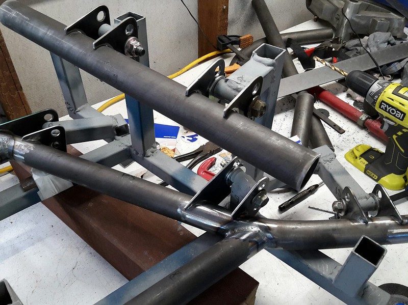
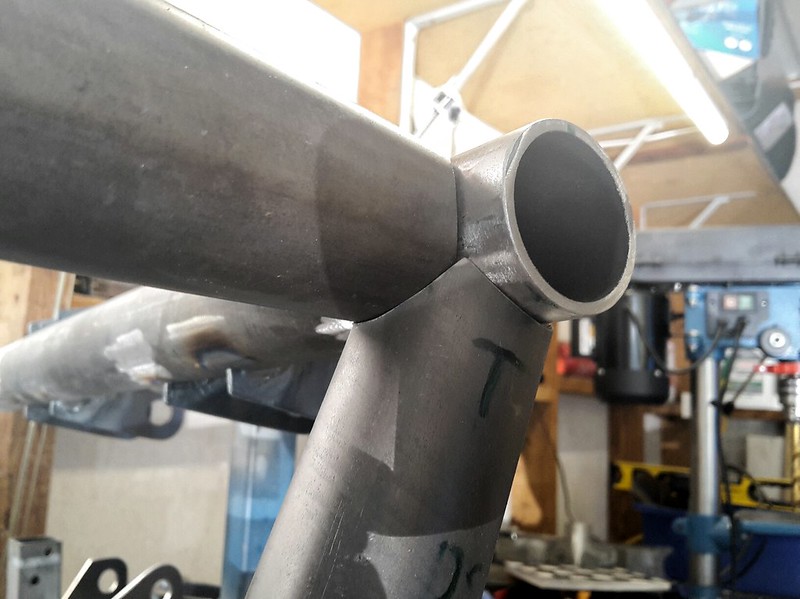
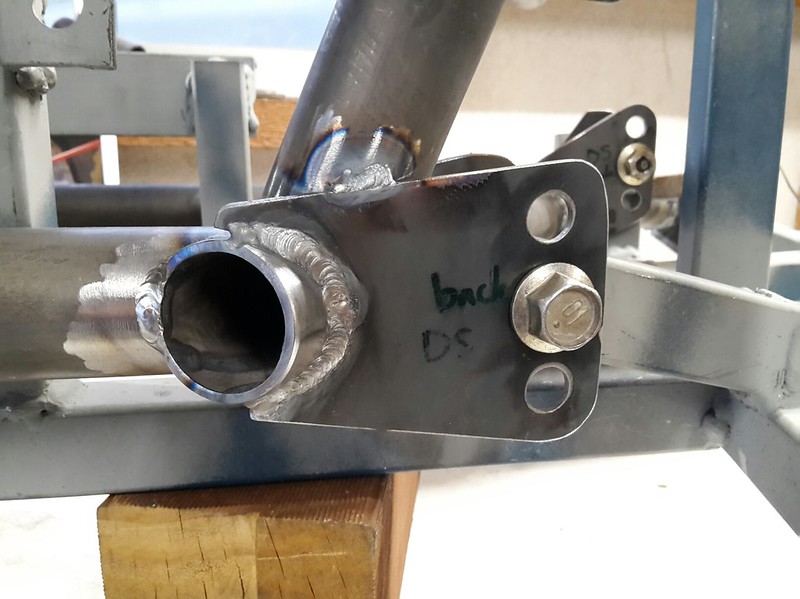
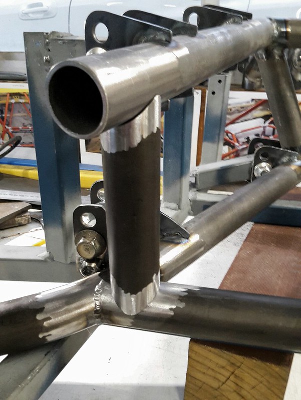
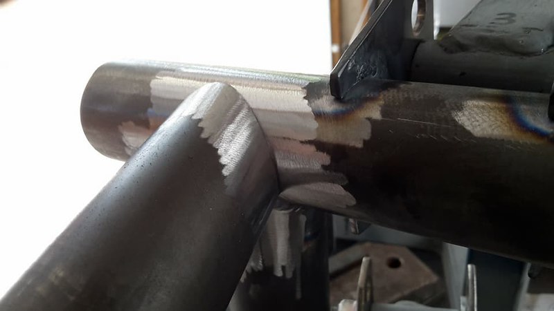
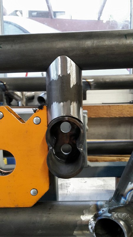
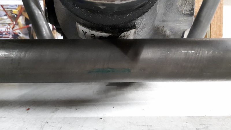
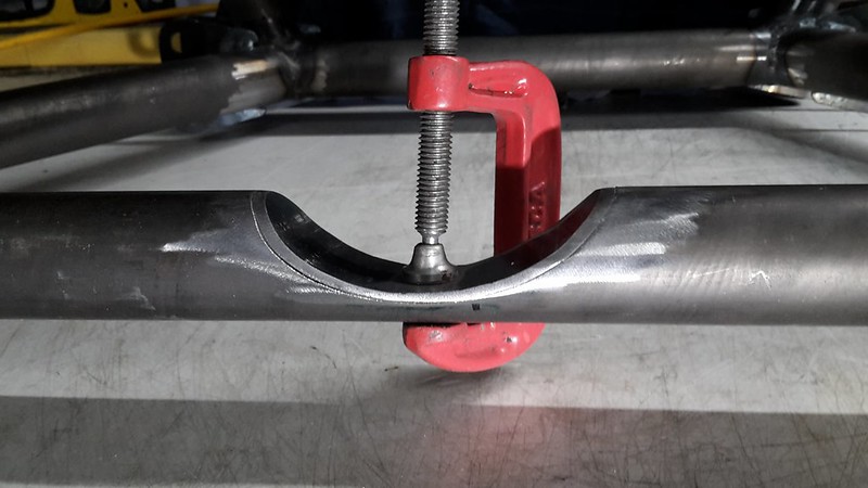
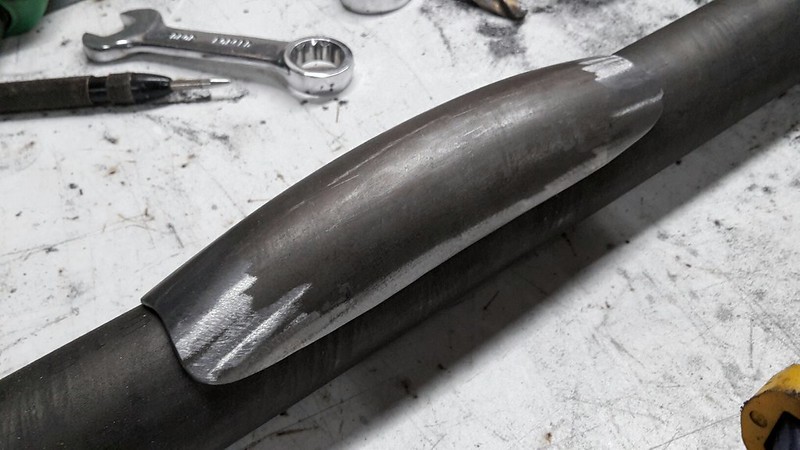
Picking up where we left off I started by fixing my issue with the notched tube for diff clearance.  
 
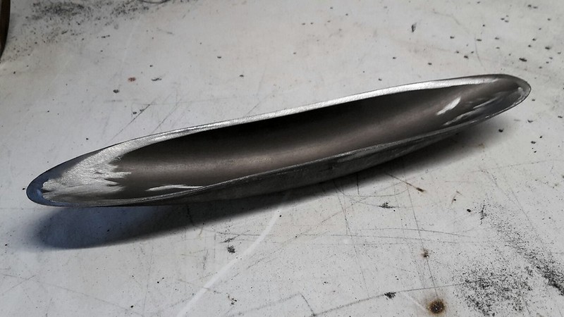
I took a unused bend I had lying around from building the roll cage and neatly sliced the bend off just above the half way mark.
 
40117208220_3c3454b085_c.jpg
 
I then had to notch the ends of it until if fit snug on a flat piece if tube.
 
41880316502_63dabfa865_c.jpg
 
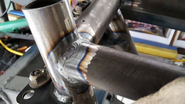
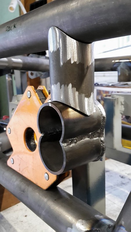
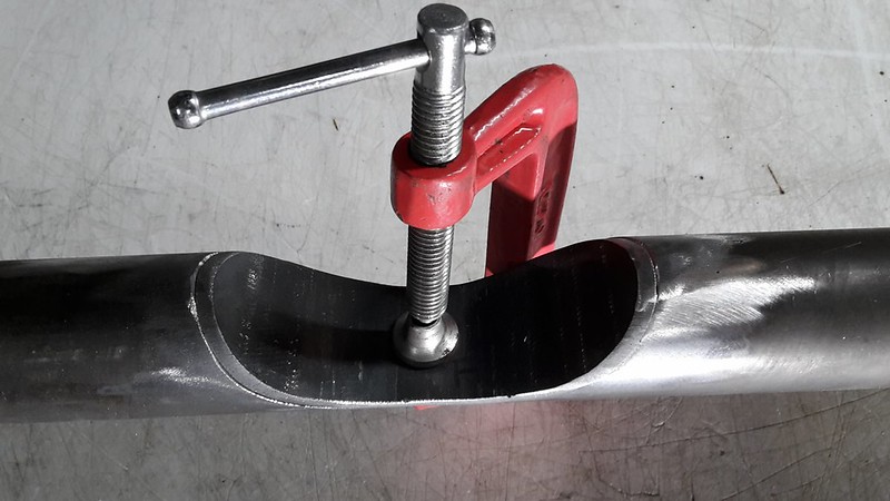
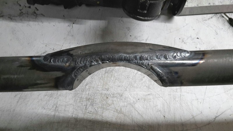
Then after a whole lot of welding it was all in place.
 
40117207170_ff4df14857_c.jpg
 
28053695278_4172657bdd_c.jpg
 
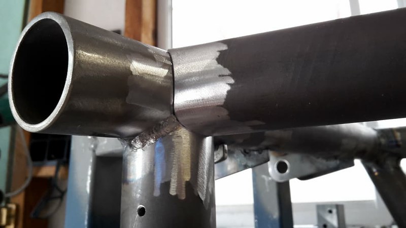
I'm happy with how it has turned out and I have no concern at all that the tube may now be weaker. Looking at the FEA simulation this is one of the least stressed tubes in the whole structure.
 
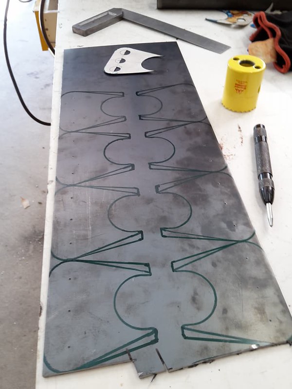
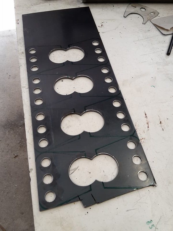
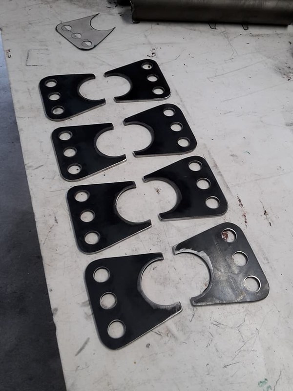
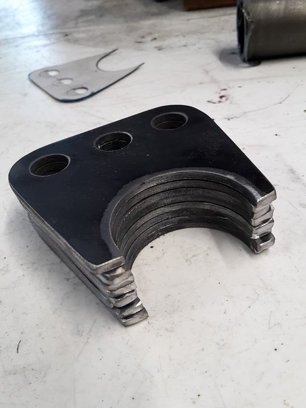
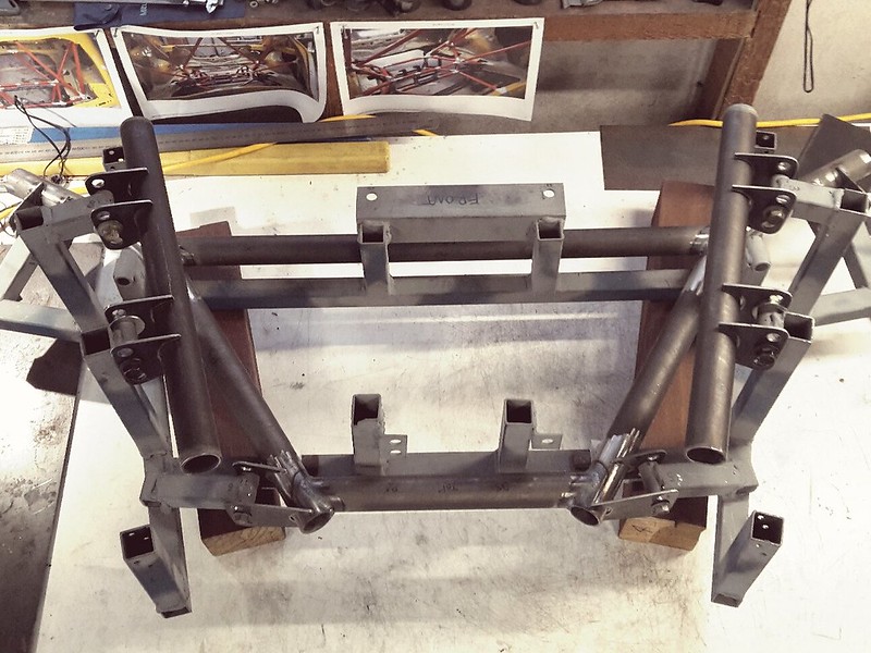
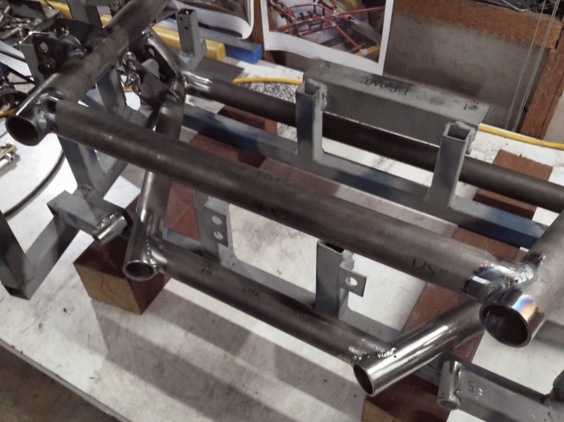
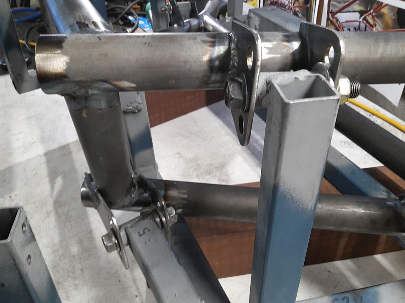
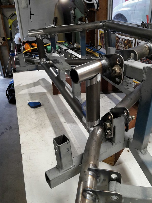
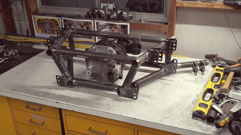
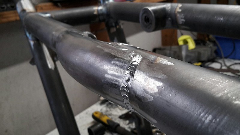
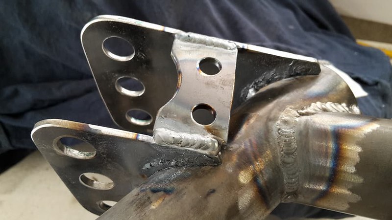
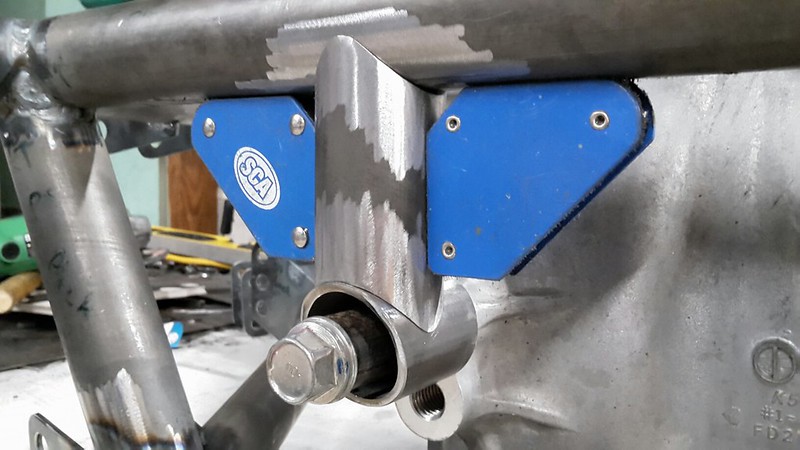
Next up I decided to add a few little extra braces for some of the longer tabs where the control arms attach, just to make sure they would be stiff enough.
 
40117043840_894f8c78d4_c.jpg
 
Then welded them into position. Easy job but still eats up a lot of time.
 
40117043730_f226b3817c_c.jpg
 
40117043940_dfe4abdc99_c.jpg
 
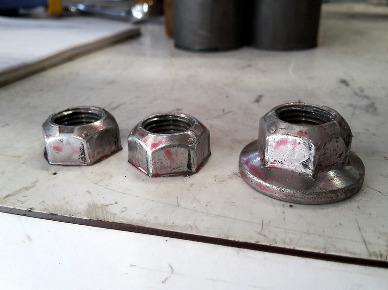
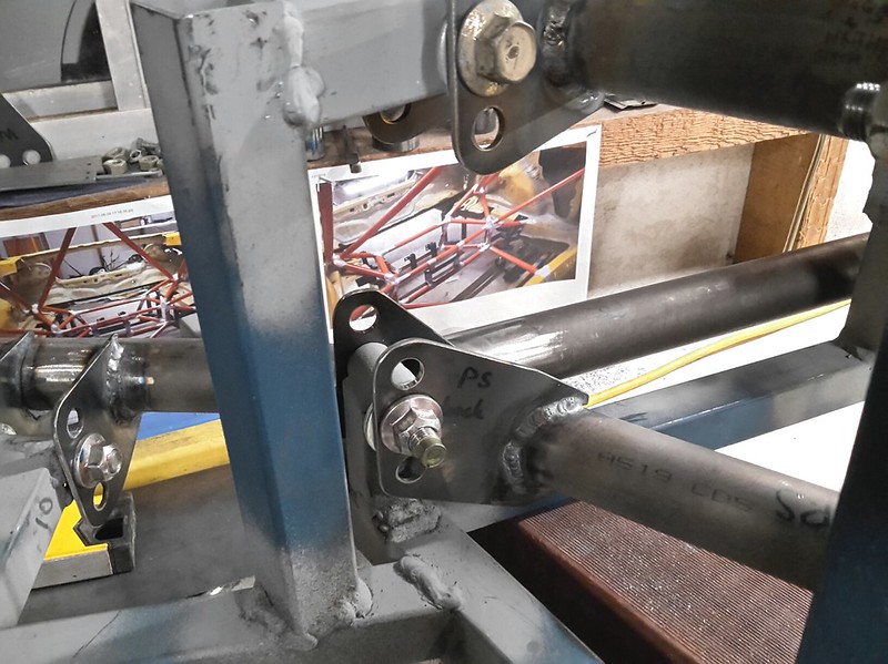
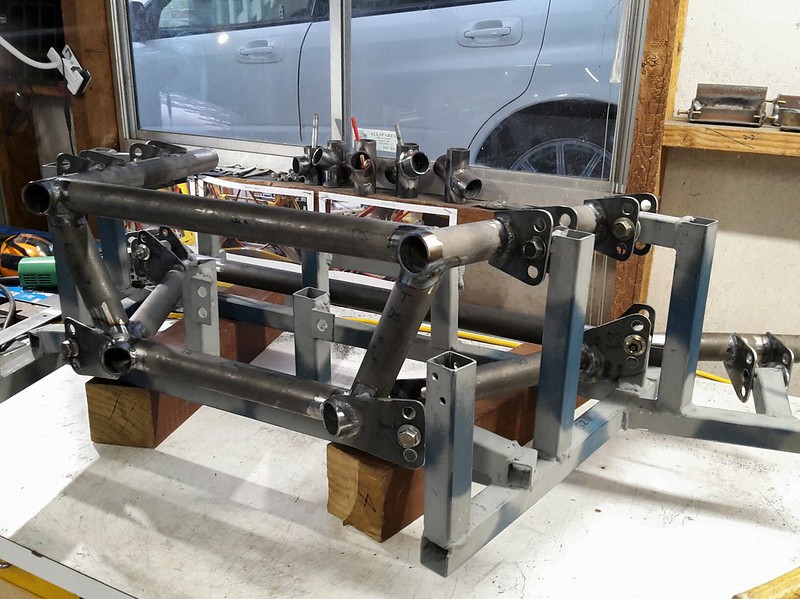
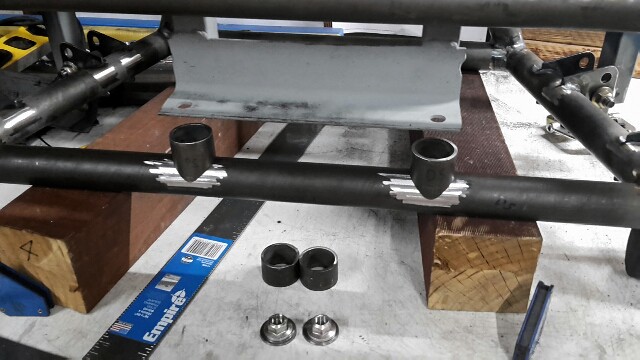
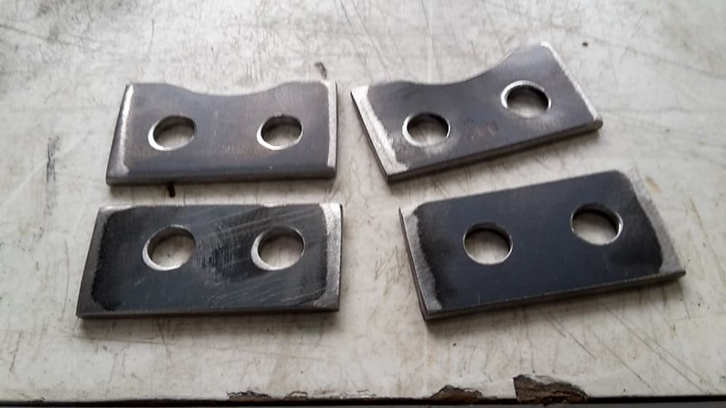
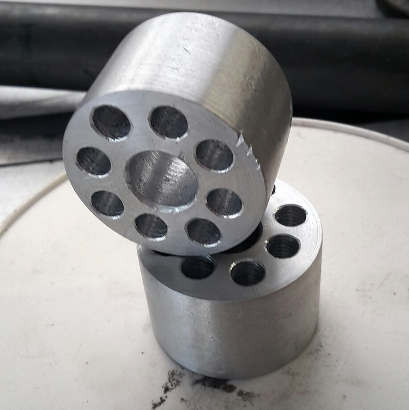
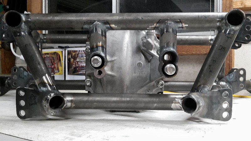
With that done it was back to mounting the diff. My mate turned up some aluminium spacers for me so I can adjust the height at the front diff mounts. They felt a little heavy so I drilled them out a little, turned out to be a complete waste of time though as not much weight was saved.
 
40117207230_cc89fe9ddd_c.jpg
 
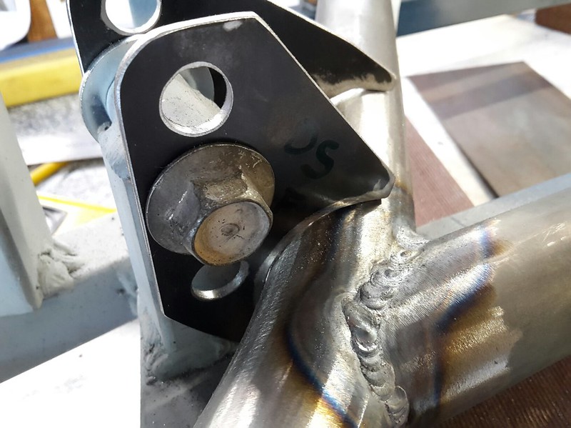
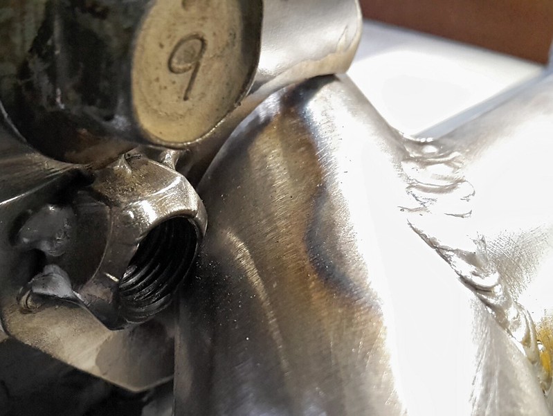
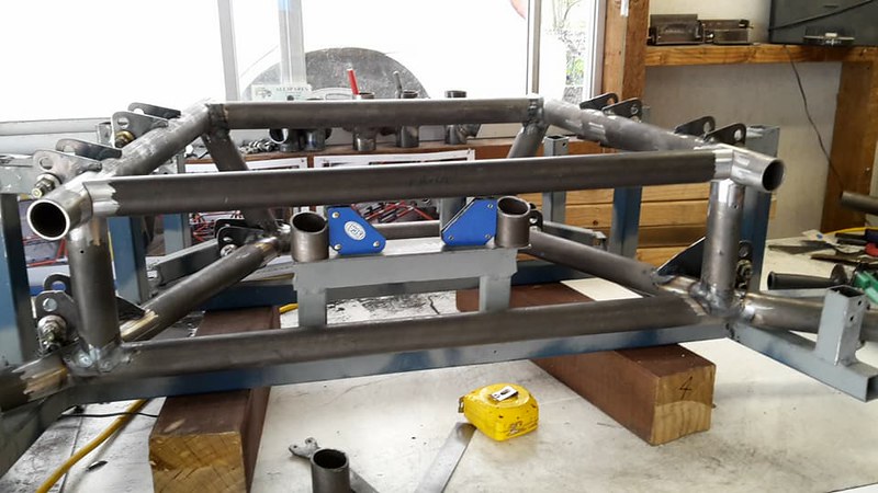
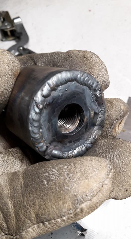
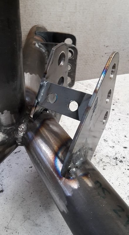
I then completed the welds on the rear diff mount I had previously tacked into position.
 
28053696858_0a0d969d1e_c.jpg
 
and then began to fabricate the final diff mount.
 
40117210490_652b6b3ab7_c.jpg
 
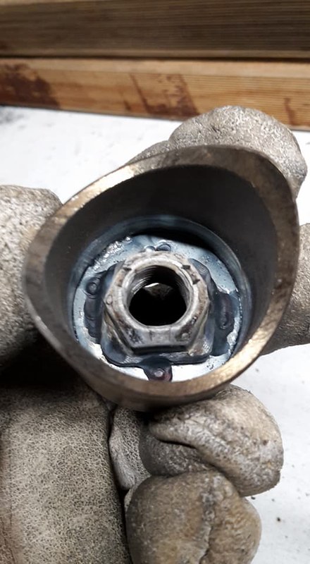
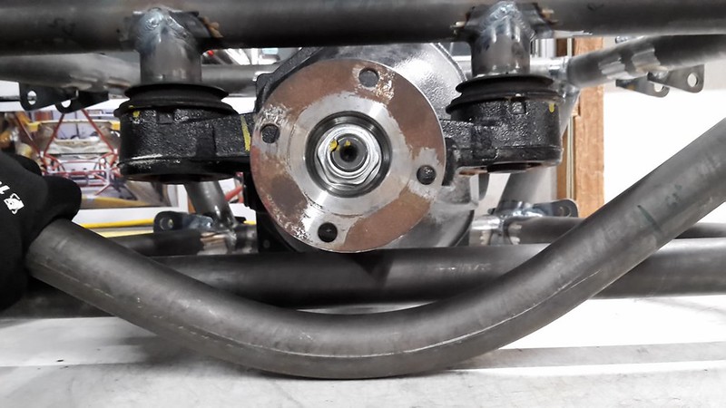
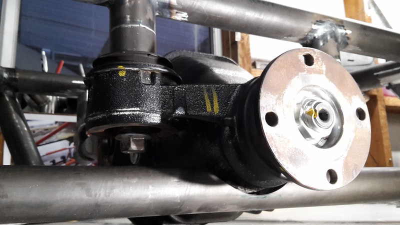
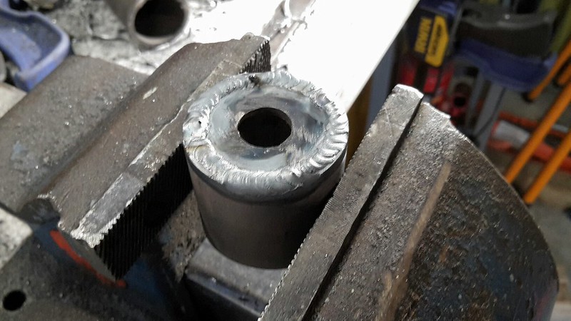
You may notice the spacer behind the bolt. I need to go buy some shorter bolts to mount the diff as the stock ones are super long so they can pass through the large rubber bushings in the stock frame. My diff will be solid mounted all the way, actually there will be no rubber bushings in the entire car.
 
41025269685_07b1b131d4_c.jpg
 
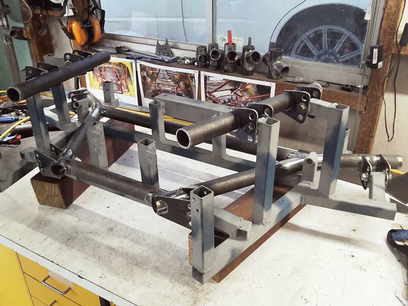
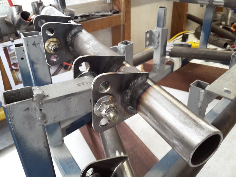
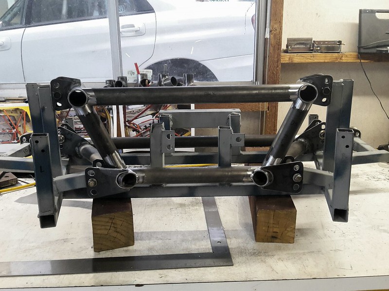
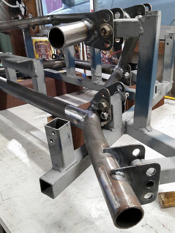
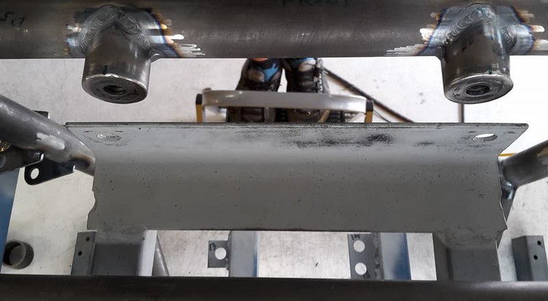
With all the welding now complete you can see how the diff moves up 26mm by removing those spacers at the front and swapping mounting holes at the rear.
 
27055182497_16e8f2b177_c.jpg
 
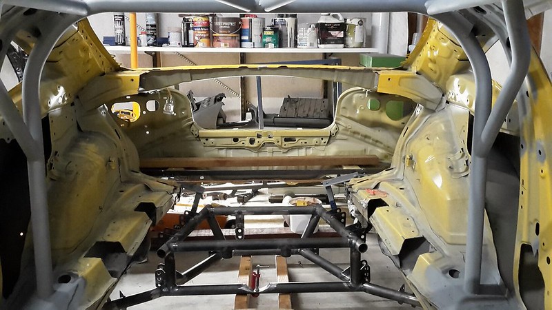
So that's where I got up to before running out of time. A great result as its basically ready to go back into the jig and then get welded into the car.
 
I was thinking I might add a couple of tabs on the back to attach the uprights for the rear wing, I have also been toying with the idea of building a aluminium honeycomb impact attenuator to mount behind this cradle and extending to the rear bumper, you see them a lot in Jap racing series and FSAE cars. 

Follow me on Insta: @brzdiy


0 user(s) are reading this topic

0 members, 0 guests, 0 anonymous users