Jump to content


Photo

seeking advice: DW300 vs WRX FPC vs stock wiring


  • Please log in to reply
11 replies to this topic

#1 andrew_k

andrew_k

    Regular Member

  • Members
  • PipPipPip
  • 438 posts
  • Location:Kyneton, VIC

Posted 28 February 2016 - 10:14 PM

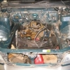
I've got the wrx donor rear cabin harness next to my foz equiv here and while i'm merging them it seems a great time to upgrade the piddly little wires supplying the fuel pump with something that can actually support the amp draw of upgraded pumps. I have a Wally 255 currently, but I don't trust it enough to use it in the new build and since I'm running 850cc injectors and north of 20psi I figure a DW300 will be a suitable replacement.


Question time:

  - WRX fuel pump controller is on 16AWG cable, on a shared 30A fuse. Anyone know how much current draw it can cope with, specifcally due to component limits? It's got a healthy sized heatsink on it, which I could easily add a 12v GPU fan to if overheating is the primary potential problem.

  - Do the earlier subies such as GC8 and SF5 run 100% duty cycle, or is the FPC integrated into the ECU?

  - Could I low-pass-filter the FPC pwm signal, and use that to switch a big relay so the fuel pump bypasses the FPC when at 100% duty? That would sidestep the potential current problem while still retaining the PWM control for reduced pump rates... if that DOES work, why don't I see people doing it? There must be a gaping flaw in that approach that I'm missing. Possibly the relay switching causes a momentary lean condition.


Plz advise while I still have this shit spread out on the lounge room floor. It would be so easy to depin the connectors and replace all the FPC/pump power lines with 12AWG right now, but once it's taped back up I know I'll never get around to doing it.


#2 Matt

Matt

    "THERMAL MANAGEMENT SPECIALIST"

  • Members
  • PipPipPip
  • 4,380 posts
  • Gender:Male
  • Location:Lake Maquarie NSW
  • Interests:Things, music, stuff & whatchamacallits

Posted 01 March 2016 - 08:20 PM

Look at my thread and copy me...youll have no issues what so ever

8 gauge..or atleast 6mm cable from the battery direct to the pump via a relay...and the same cable to the fpc soldered to the wire coming out

Then a big cable soldered in parallel to the earth to the fpc

Works wonders

Volt drop is the big killer in the system...the fpc can handle my setup with ease...no fan required

Oh and use the old positive from the fpc to power the relay and a straight earth to the chassis for the other side...but use a kill switch on the earth for the relay as it wont turn off due to the fpc innards

The neg from the fpc does all the switching...so itll still do the 33/66/100 shizz and work as stock
I used 8 gauge cable if you were interested aswell..big 30A fuse at the battery and a bolted terminal relay 100A relay or 200A narva to switch it all as its the lowest amp relay with proper bolted terminals

#3 Matt

Matt

    "THERMAL MANAGEMENT SPECIALIST"

  • Members
  • PipPipPip
  • 4,380 posts
  • Gender:Male
  • Location:Lake Maquarie NSW
  • Interests:Things, music, stuff & whatchamacallits

Posted 01 March 2016 - 08:23 PM

Send me a pm with your number if intersted and ill send you some diagrams and pics

#4 Jimbo

Jimbo

    Livin' the Legacy

  • Members
  • PipPipPip
  • 2,771 posts
  • Gender:Male
  • Location:B'town

Posted 01 March 2016 - 08:29 PM

bcf8bf316de255dfbd74e6e872bc84a2_400x400


'04 Liberty GT Premium "The Sprog Chariot"


#5 patttyfox

patttyfox

    Regular Member

  • Members
  • PipPipPip
  • 747 posts
  • Gender:Male

Posted 01 March 2016 - 08:42 PM

bcf8bf316de255dfbd74e6e872bc84a2_400x400


That's what I thought when Matt explained it to me the first time round..


Sent from my iPhone using Tapatalk

#6 andrew_k

andrew_k

    Regular Member

  • Members
  • PipPipPip
  • 438 posts
  • Location:Kyneton, VIC

Posted 01 March 2016 - 09:26 PM

Sick, thanks for the details Matt! 

I'll go through your thread tomorrow and sketch up my planned wiring based on what you've done. Will PM you if my brain explodes :)


I've got 10AWG (30A) wire and suitable connectors already which I'll probably use, as I don't expect the FP to go over 15-16A.  The voltage drop for 5m of 10AWG with 15A of 12v going through it is ~0.43v, and for the same power through 8 AWG would only drop ~0.31v. Money's tight enough that I'll wear that extra drop rather than fork out more dollars right now. I will skip replacing the original wire though and run new power in parallel, those OEM connectors don't look up to the task at all, esp the one under the rear seat.


Only thing that I don't understand in your initial explanation is about earthing the FP relay via a kill switch. I understand that the earth from the FPC is a pulse width modulated signal so will be above ground when the pump is at less than 100%, but what triggers a kill switch if I add one? Is that a manual safety you're recommending I add in case of a fire?


#7 andrew_k

andrew_k

    Regular Member

  • Members
  • PipPipPip
  • 438 posts
  • Location:Kyneton, VIC

Posted 01 March 2016 - 09:26 PM

DOH double poast. Stupid buggy laptop trackpad.


#8 Matt

Matt

    "THERMAL MANAGEMENT SPECIALIST"

  • Members
  • PipPipPip
  • 4,380 posts
  • Gender:Male
  • Location:Lake Maquarie NSW
  • Interests:Things, music, stuff & whatchamacallits

Posted 02 March 2016 - 05:15 AM

Yep i know....ots a lot to take in lol

But it works....and its been done countless times now on big power cars with great success

Now

Your finger triggers the kill switch....as the relay will not disengage itself and will suck your battery down when the cars off

Or else find a suitable ignition powered wire and use that for the relay and itll turn itself off. ..i wanted a kill switch and its a good point to have one (one thatll kill the pump)

My pump hits 20A a lot and the FPC has no issues at all

You HAVE to run the positive from the battery to bypass the FPC positive or else it wont work anywhere near aswell

You lose a lot of volts through the FPC....the direct feed remedies this completely

But you can still run the negative wire in parallel with the FPC to fix the small wire issue


And also...lol...i bypass all connectors at the pump and run through connectors through the tank lid and direct to the pump

So my positive wire goes battery>Relay>through connector>pump.....no oem shit to stuff up

#9 Matt

Matt

    "THERMAL MANAGEMENT SPECIALIST"

  • Members
  • PipPipPip
  • 4,380 posts
  • Gender:Male
  • Location:Lake Maquarie NSW
  • Interests:Things, music, stuff & whatchamacallits

Posted 02 March 2016 - 05:26 AM

Screenshot_2015-07-25-08-29-23.png

#10 bigBADbenny

bigBADbenny

    New Member

  • Members
  • Pip
  • 89 posts
  • Gender:Male
  • Location:Hollywood, Melbourne
  • Interests:Family Photography Cars Bicycling

Posted 02 March 2016 - 07:37 AM

There's a big thread on this subject on LGT, recently updated the wiring diagram to resolve battery drain when the car is switched off. :)
http://legacygt.com/...0&highlight=HKB

When doing this mod, it's a great opportunity to slightly twist all the blade pins in the oe plugs to promote continuity, especially the pump top plug under the fuel tank cover...
MY07 GT-B 6MT OBP WAG

#11 andrew_k

andrew_k

    Regular Member

  • Members
  • PipPipPip
  • 438 posts
  • Location:Kyneton, VIC

Posted 02 March 2016 - 08:30 AM

Nice one, thanks for the tips gents, more reading to get through tonight it seems!


#12 duncanm

duncanm

    wha' who ?

  • Members
  • PipPipPip
  • 2,012 posts
  • Gender:Male
  • Location:Sydney

Posted 02 March 2016 - 10:59 AM

The important thing to note is the high current path...


Battery - Relay - Pump+ - Pump- - FPC pin 6 - (FPC) - FPC Pin 5 - GND.


Fatten up that pin 6 to Pump wire, too.


0 user(s) are reading this topic

0 members, 0 guests, 0 anonymous users