Jump to content


Photo

Joel's BRZ

#becauseracecar

  • Please log in to reply
583 replies to this topic

#201 JDWhiteWRX

JDWhiteWRX

    Regular Member

  • Members
  • PipPipPip
  • 590 posts
  • Gender:Male
  • Location:Royal National Park, NSW

Posted 19 December 2018 - 02:10 PM

I kind of did that already with my wrx, it is mostly carefully selected off the shelf parts. It's a really nice package for gravel racing and motorkhanas but it was never going to be all that competitive for time attack.


This build is just a natural progression for me and making things where possible instead of buying off the shelf parts has kept the costs pretty low, I think I just hit $3.5k total spend when I bought the RX8 bits.


There are some expensive bits I need to buy soon like the motor and gearbox and probably some wheels, that will drive the budget up a lot.


Follow me on Insta: @brzdiy


#202 JDWhiteWRX

JDWhiteWRX

    Regular Member

  • Members
  • PipPipPip
  • 590 posts
  • Gender:Male
  • Location:Royal National Park, NSW

Posted 06 January 2019 - 11:28 AM

Happy new year to you all.
 
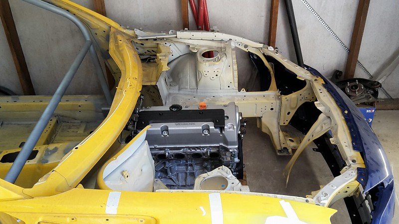
Not a lot has been happening with the car with Christmas and all that but yesterday I did manage a full day of work on the front suspension.
 
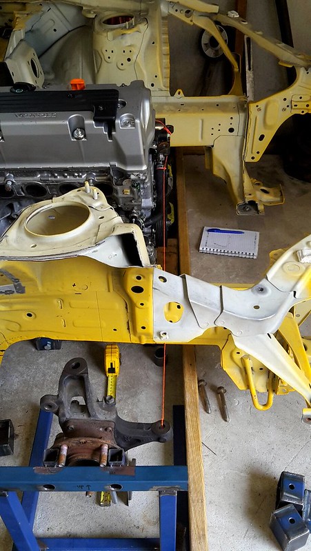
After lots of back and forth on the design I finally came up with a method to attach the inner control arms to the chassis. Similar to the rear I wanted to be able to adjust the geometry as much as possible.
 
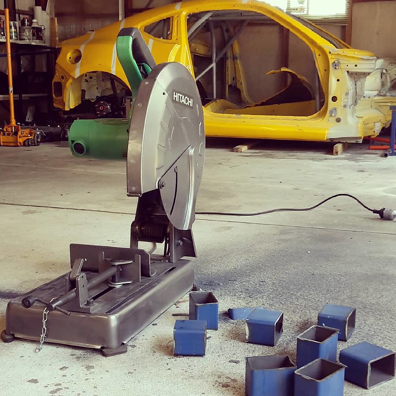
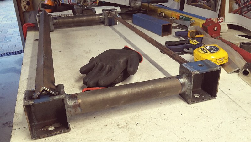
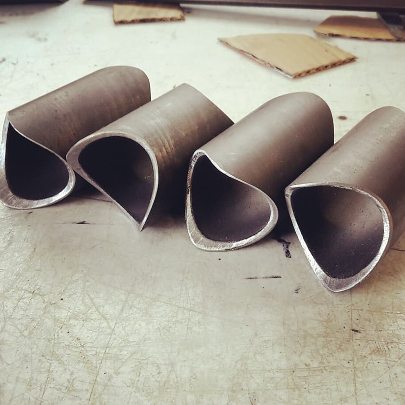
I started out with cutting up some 75mm x 50mm x 3mm rectangular box steel.
 
32748233038_2f7da60c41_c.jpg
 
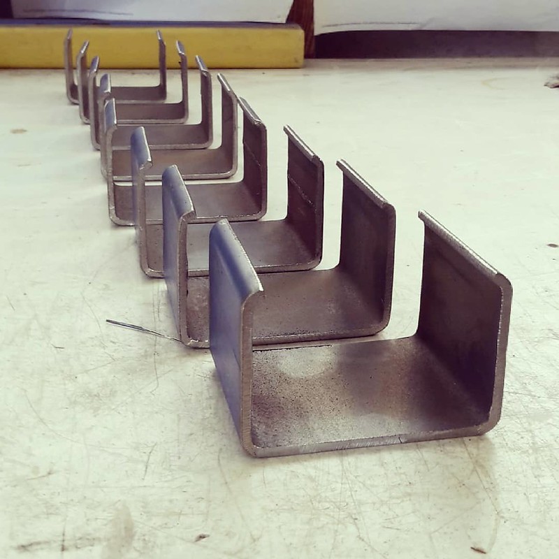
Then I cut out one face of the box. There are 8 in total which is enough to do upper and lower control arm mounts on both sides of the car.
 
32748232938_6ee39b164f_c.jpg
 
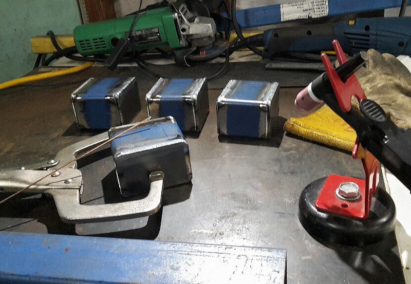
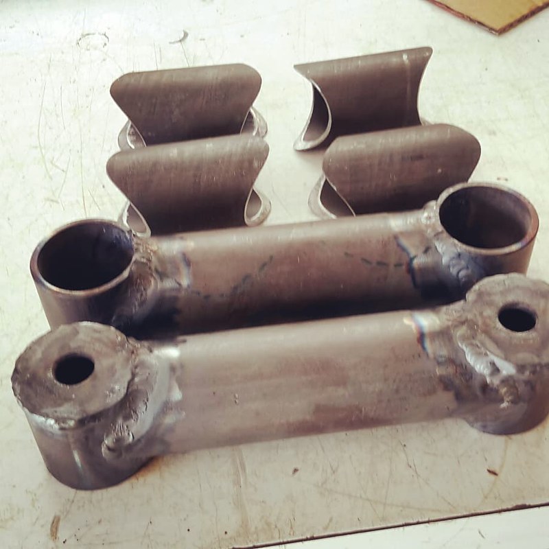
Then I had to cut out 16 squares from 3mm sheet to box in the open faces.
 
46570267802_90a36602d5_c.jpg
 
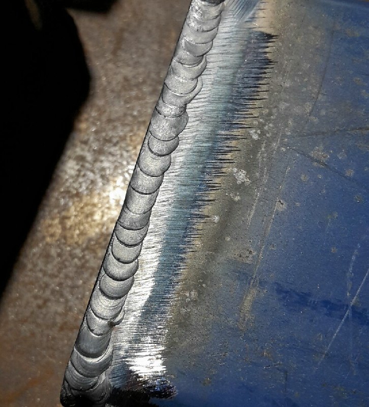
I then tig welded them all and it took a really long time! I calculated after I had finished that I had welded 2.8m in length. Anyway it was really good practice and by the time I welded a couple my settings were dialed in perfectly and my welds were very consistent.
 
39657665293_c635e5c606_c.jpg
 
I also beveled both faces before welding for maximum penetration.
 
39657665243_a39105f3f0_c.jpg
 
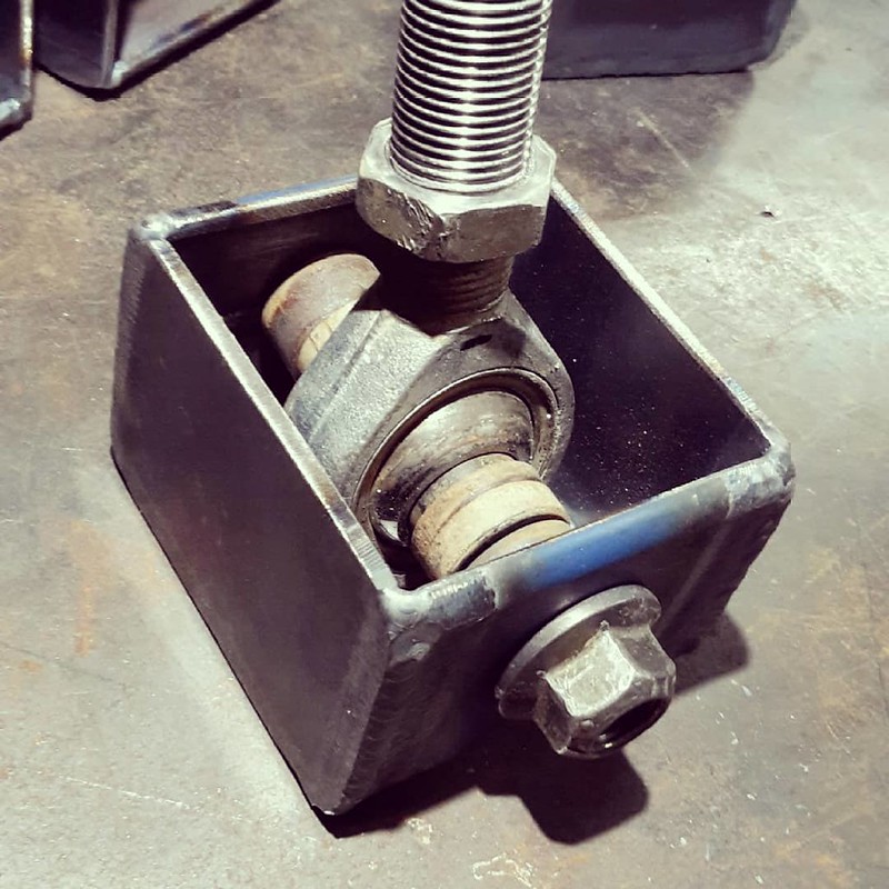
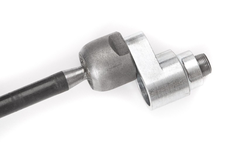
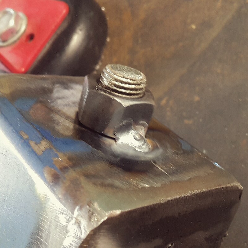
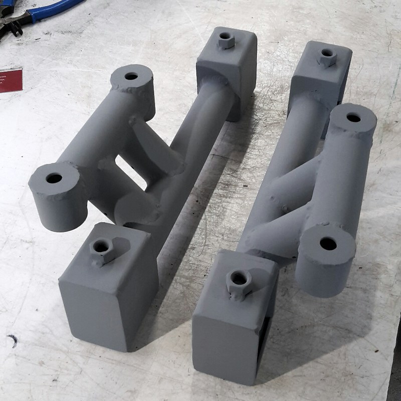
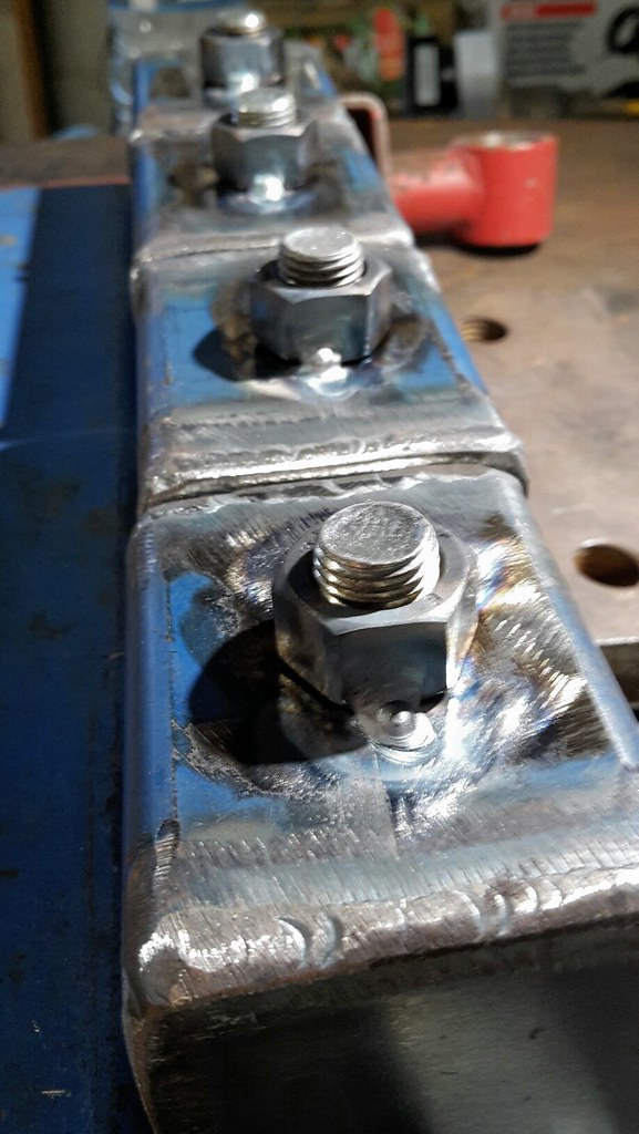
So this is the finished product before it gets welded into the chassis. The rod end is just an old one I had from my wrx to show how it works. I will be using one size smaller than this when I do my bulk order for all the control arms. 
 
32748234488_9de19f89e8_c.jpg
 
They will be mounted in the chassis with the bolt running vertical so the rod end is sitting horizontal. This will allow me to use spacers to position the rod end on the bolt at different heights to adjust the pivot height which changes control arm angles for camber gain and roll center.
 
Using the rod ends also allows me to adjust the length of the arms for static camber and caster adjustment.

Follow me on Insta: @brzdiy


#203 El_Freddo

El_Freddo

    Rock'n the old Skool

  • Members
  • PipPipPip
  • 2,236 posts
  • Gender:Male
  • Location:Bridgewater/Central Vic/semi-retired nomad
  • Interests:Subarus, 4wd'n Subarus, travelling Subarus, Tinkering... I could go on!

Posted 06 January 2019 - 02:26 PM

I’m glad you’ve got the whole concept nailed down! I think I follownthat you’re saying, just that it seems a bit against convention with the vertical bolt orientation. I would’ve thought that’d be horizontal with several mount points as you have it in the rear end. I guess adjustment is more sensitive up front compared to the rear’s.

And just magic on those welds Josh! I wish I had the time and patience for a job like this. My L series off-roader would be MINT with this sort of ability at my disposal!

Cheers

Bennie
"The lounge room is not a workshop..."
https://www.imageshack.us/i/po1BKrxbj
1BKrxb.jpg
El Freddo's Pics    -    El_Freddo's youtube

#204 JDWhiteWRX

JDWhiteWRX

    Regular Member

  • Members
  • PipPipPip
  • 590 posts
  • Gender:Male
  • Location:Royal National Park, NSW

Posted 06 January 2019 - 03:50 PM

I think the reason you mostly see people mounting the rod ends vertically is you have unlimited motion in this direction whereas horizontal mounting limits the movement because at some point (11 degrees) the bearing will contact the housing.


With a 340mm control arm 11 degrees gives me way more wheel travel than I am ever going to use in a time attack car so its a non-issue. The nice thing is the infinite vertical adjustment of the rod ends I now have within the boxes whereas with my rear end setup I only have 3 steps to choose from.


What I might do with the rear is slot the upper 2 holes which are the ones I'm most likely to use and make up some slugs for mounting the control arms. You can see these slugs below have holes at different heights for fine tuning the rod end position.


46625436281_e6c4c309d1_z.jpg


Follow me on Insta: @brzdiy


#205 JDWhiteWRX

JDWhiteWRX

    Regular Member

  • Members
  • PipPipPip
  • 590 posts
  • Gender:Male
  • Location:Royal National Park, NSW

Posted 03 March 2019 - 09:31 PM

Alright some big news for those not following on Instagram, the engine for this project has been selected, purchased and collected.
 
After a lot of consideration I decided to go with a Honda K24 which will be turbocharged. Bang for buck you can not beat this engine especially here in Australia where these motors are dirt cheap and readily available. I paid $450 for this engine with only 90k km's on it at a wrecking yard.
 
After getting it home I removed the intake and exhaust manifolds and gave it a pressure wash.
 
47265869851_23f9985336_c.jpg
 
Under the WTAC rules I am building to the engine is allowed to be moved back so that the rear of the engine is no more than 50mm rearward of the original firewall.
 
32324047957_097e414e17_c.jpg
 
So to make the most of this rule I basically cut the original firewall out and once the motor is in its final position I will have to make up a new firewall from sheet metal.
 
33390076768_9d08a55fc1_c.jpg
 
With that done I then slid the engine into its intended final position.
 
40301290283_1a0a773cbf_c.jpg
 
I am really happy with where it is sitting, most of the weight is behind the front wheels and there is loads of space for a really well ducted intercooler/radiator combo. It will also leave me enough space for the steering rack to sit in front of the engine.
 
40301290263_5d00cec778_c.jpg
 
The reason I have purchased the motor before finishing the front suspension is that the lower control arm mounts will be part of the front cross-member which will also contain the engine mounts. So I basically had to buy an engine to get that finished.

Follow me on Insta: @brzdiy


#206 Barbbachello

Barbbachello

    Touring Bruce

  • SubyClub Area Rep
  • PipPipPip
  • 6,449 posts
  • Gender:Male
  • Location:Mehico
  • Interests:Docking

Posted 04 March 2019 - 10:05 AM

Skitz as always. Whats the plan for a gearbox? Stock BRZ?


tIeW8DE.png


#207 Niko

Niko

    Member's Member

  • Members
  • PipPipPip
  • 7,511 posts
  • Gender:Male
  • Location:Sydney City

Posted 04 March 2019 - 10:16 AM

Awesome work Joel, we were wondering how you were able to do this within the rules, may as well take advantage of them.


Stock BRZ box is glass over 300kw, surely going something stronger.


#208 JDWhiteWRX

JDWhiteWRX

    Regular Member

  • Members
  • PipPipPip
  • 590 posts
  • Gender:Male
  • Location:Royal National Park, NSW

Posted 04 March 2019 - 10:45 AM

At this stage I plan to use a Honda S2k 6-speed.

There are adapters available for the following:

S2k
E36
350Z
RX8
MX5
BRZ/86

Follow me on Insta: @brzdiy


#209 Barbbachello

Barbbachello

    Touring Bruce

  • SubyClub Area Rep
  • PipPipPip
  • 6,449 posts
  • Gender:Male
  • Location:Mehico
  • Interests:Docking

Posted 04 March 2019 - 10:54 AM

Spoilt for choice. Are you moving the driving position as well? Would think moving the engine back that far would also move the shifter back heaps too?


tIeW8DE.png


#210 JDWhiteWRX

JDWhiteWRX

    Regular Member

  • Members
  • PipPipPip
  • 590 posts
  • Gender:Male
  • Location:Royal National Park, NSW

Posted 04 March 2019 - 01:14 PM

Yeah everything is moving! :)


Follow me on Insta: @brzdiy


#211 El_Freddo

El_Freddo

    Rock'n the old Skool

  • Members
  • PipPipPip
  • 2,236 posts
  • Gender:Male
  • Location:Bridgewater/Central Vic/semi-retired nomad
  • Interests:Subarus, 4wd'n Subarus, travelling Subarus, Tinkering... I could go on!

Posted 04 March 2019 - 07:43 PM

Geez!
"The lounge room is not a workshop..."
https://www.imageshack.us/i/po1BKrxbj
1BKrxb.jpg
El Freddo's Pics    -    El_Freddo's youtube

#212 JDWhiteWRX

JDWhiteWRX

    Regular Member

  • Members
  • PipPipPip
  • 590 posts
  • Gender:Male
  • Location:Royal National Park, NSW

Posted 14 March 2019 - 02:46 PM

What I am struggling with now is the location of the steering rack, I have not purchased a rack yet but I do have a electric motor that pumps the fluid out of an Opel/Holden Astra.
 
At the moment the steering rack needs to sit about where the front of the crank pulley is and I still need to add a small pulley to the front of the crank for the dry sump.
 
I have two ideas at the moment to solve this but am open to suggestions from you guys.
 
My first idea was to use those rack offset spacers that drifters use to step the rack forward but still keep the tie rods where they need to be, this will gain me about 25mm.
 
47323001512_5b7b4167e5_c.jpg
 
The other idea is to move the front wheels forward i.e. extend the wheelbase. This will obviously move the tie rod connection point on the knuckles forward buying me some more space for the steering rack. I am not sure if I am overlooking any downsides to extending the wheelbase though? Normally that would be rather extreme modification but since I am already re-designing the whole front suspension its actually very easy for me to do. Also I have noted in a video on youtube that the Subaru GT300 BRZ extended their wheelbase by 35mm for the 2017 season.
 
32434130497_ed561f9719_c.jpg
 
The orange string line in this photo shows where the rack needs to be.
 
32432675197_260611c839_c.jpg

Follow me on Insta: @brzdiy


#213 JDWhiteWRX

JDWhiteWRX

    Regular Member

  • Members
  • PipPipPip
  • 590 posts
  • Gender:Male
  • Location:Royal National Park, NSW

Posted 25 March 2019 - 12:48 PM

I have made some more progress on the front cross-member and double wishbone conversion. The lower control arm mounts are now finished.
 
Once I had worked out the control arm pivot positions I moved the pieces I had made previously onto the bench to get everything measured up and square. I then tack welded some scrap metal to them to hold them in place.
 
46545691095_2c4244fb47_c.jpg
 
Then I had to position it in the car in the correction spot and take some measurements for the tube required to join it together.
 
47460983531_ca1dc2b3e8_c.jpg
 
Then with a bunch of tube notching, these are very short so I had to do a complete cut notching two pieces in one go. Usually I do one end at a time to the hole saw is not working so hard.
 
32519114297_d546ab29ef_c.jpg
 
These then join to the parts I had made previously which bolt into the factory front cross-members mounts on the chassis rails.
 
47460917381_fb7840a293_c.jpg
 
I then tacked it all together on the car before taking it back out so I could weld it on the bench.
 
47460917361_d4a82c435c_c.jpg
 
I also added some captive nuts to make adjustments to the geometry easier.
 
33584552298_d37fb2b179_c.jpg
 
Even though I will be adding to these pieces later I decided to cold gal them to keep the surface rust away. I hate cleaning off surface rust.
 
33584552278_7fea35c1ee_c.jpg
 
Back on the car.
 
33584552288_bb2b595e93_c.jpg
 
The rod ends will be mounted horizontally with spacers or varying thickness above and below. This allows me to change the inner pivot height over a reasonable range to tune the camber gain and roll center to my liking.
 
33584554428_a5b4920694_c.jpg
 
Next job will be the upper control arm mounts.

Follow me on Insta: @brzdiy


#214 El_Freddo

El_Freddo

    Rock'n the old Skool

  • Members
  • PipPipPip
  • 2,236 posts
  • Gender:Male
  • Location:Bridgewater/Central Vic/semi-retired nomad
  • Interests:Subarus, 4wd'n Subarus, travelling Subarus, Tinkering... I could go on!

Posted 25 March 2019 - 07:36 PM

Once again neat tube work Josh!

I’m guessing that these pieces will end up being tied into the upper control arm mounts and an engine crossmember to make the whole front end very rigid, correct?

I’m looking forward to this!

When do other things start going on/back in the vehicle - any rear end going in/wheels going on soon?

Cheers

Bennie
"The lounge room is not a workshop..."
https://www.imageshack.us/i/po1BKrxbj
1BKrxb.jpg
El Freddo's Pics    -    El_Freddo's youtube

#215 JDWhiteWRX

JDWhiteWRX

    Regular Member

  • Members
  • PipPipPip
  • 590 posts
  • Gender:Male
  • Location:Royal National Park, NSW

Posted 25 March 2019 - 09:29 PM

Once again neat tube work Joel!

I’m guessing that these pieces will end up being tied into the upper control arm mounts and an engine crossmember to make the whole front end very rigid, correct?

I’m looking forward to this!

When do other things start going on/back in the vehicle - any rear end going in/wheels going on soon?

Cheers

Bennie


Cheers Bennie.


The upper control arms use the same little rectangular boxes but they will be integrated into the existing frame rails. The lower arm mounts make up part of the front cross-member that will also support the engine and steering rack. There will be tube coming in from the roll cage that ties into the shock mounts and some kind of "X" brace in front of the motor that ties the whole thing together. There is no detailed design at this stage, just some ideas in my head.


I need to make control arms for both the front and rear of the car and then I can get some wheels so at least its then a rolling shell. There is still a lot to do and I don't really get a lot of time to play with the car but the main thing is I enjoy the whole process and eventually it will get done.


Joel.


Follow me on Insta: @brzdiy


#216 Asymmetry

Asymmetry

    New Member

  • Members
  • Pip
  • 51 posts
  • Gender:Male

Posted 28 March 2019 - 09:02 AM

Wow this is come crazy next level shit. Might as well copy the Ariel atom with the capability you have there Joel.


#217 Niko

Niko

    Member's Member

  • Members
  • PipPipPip
  • 7,511 posts
  • Gender:Male
  • Location:Sydney City

Posted 28 March 2019 - 09:31 AM

This is great Joel, awesome progress given the limited time you have to work on it.


#218 JDWhiteWRX

JDWhiteWRX

    Regular Member

  • Members
  • PipPipPip
  • 590 posts
  • Gender:Male
  • Location:Royal National Park, NSW

Posted 31 March 2019 - 09:28 PM

Thanks guys, I appreciate your comments.


I got the upper control arm mounts for the double wishbone conversion into position today. I need to convert my welder back over to MIG to weld them in but otherwise they are done.
 
Started by marking out the position of the boxes, drilling a hole at each corner and then using a combination of angle grinder and dremel to cut them out.
 
47453044402_f300a28454_b.jpg
 
Welded the nuts onto the lower side to make adjustments easier.
 
47505777611_35da08658a_b.jpg
 
Here is the view from inside the engine bay. You can see I had to trim a bit of metal above the bolts so I can get them in and out.
 
47505777571_c3b12610a3_b.jpg
 
Final photo for today showing the RX8 knuckle relative to the control arm mounts.
 
47505777591_62a2f8cca7_b.jpg
 
So I've just got remove the paint around the areas I need to weld and then weld them in. All this has to be repeated on the passenger side but I need to spin the whole shell around to do that so I'm just doing this side for now.

Follow me on Insta: @brzdiy


#219 El_Freddo

El_Freddo

    Rock'n the old Skool

  • Members
  • PipPipPip
  • 2,236 posts
  • Gender:Male
  • Location:Bridgewater/Central Vic/semi-retired nomad
  • Interests:Subarus, 4wd'n Subarus, travelling Subarus, Tinkering... I could go on!

Posted 01 April 2019 - 09:17 PM

Oooh, another big step forward! I love doing the first bit as it’s exciting and all, but dread the other side as it has to match the first side! That said I’ve never done something as sophisticated as what you’re doing here.

I just noticed your Instagram name/tag/whatever it’s called, I love it! You definitely deserve a “built not bought” sticker across the back, front and sides of this thing once it’s done!!

Cheers

Bennie
"The lounge room is not a workshop..."
https://www.imageshack.us/i/po1BKrxbj
1BKrxb.jpg
El Freddo's Pics    -    El_Freddo's youtube

#220 JDWhiteWRX

JDWhiteWRX

    Regular Member

  • Members
  • PipPipPip
  • 590 posts
  • Gender:Male
  • Location:Royal National Park, NSW

Posted 03 April 2019 - 06:09 PM

My steering rack arrived today from the USA, this is a brz rack from a LHD car but I have flipped it over so it is now front steer.
 
Gave it a quick clean and then did some measurements to see where the pivot points would be and how they would line up with my control arm pivots as this affects bump steer. 
 
Could not be happier with how well this will work. I don't have exact measurements until I remove the boots but the pivot points are around about the right spot. I will need some longer tie rod arms though since I have increased the front track a little.
 
I have done a quick mock up to show how well the pinion aligns towards the steering column. This also shows how I will be able to easily mount the rack such that it is height adjustable by adding and removing spacers under the mounting points.
 
46612109135_a2d3e955aa_b.jpg

Follow me on Insta: @brzdiy


0 user(s) are reading this topic

0 members, 0 guests, 0 anonymous users