

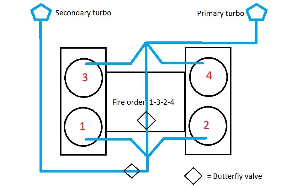
This a schematic drawing of the custom manifold i'm thinking of. In low RPM the center butterfly valve is open and the butterfly valve to the secondary turbo is closed. The header pipes to the junction with the up-pipes and the cross-pipe are of equal length. In reality the manifolds of cylinder 1-2 and 3-4 will be directly connected by the butterfly valve without a lot of pipe, so no cross-pipe but only cross valve. So on primary turbo mode all pulses arrive equally at the turbo charger. Switching to twin turbo mode the center butterfly valve will close and the butterfly valve in the secondary up-pipe will open. Then you will have real twin operation. The front bank is driving the secondary turbine while back row of cylinders is driving the primary turbo. The exhaust are all the same length, so equal pulses again.
So it will switch from single turbo charging to full parallel turbo charging.
According to some Matlab simulations the exhaust gases will reach temperatures up to 700 degree C. So I need to construct some butterfly valves that can hold these temperatures. I want to link them mechanically, one closes the other opens. This way I can still use the ECV actuator. I was thinking to fabricate them out of stainless steel, with normal steel bush bearings to prevent seizing
Or would it be better to keep the cross pipe open, or drill a hole in the valve so there still is a tiny opening after closing??
About the position of the secondary turbo butterfly, is it wise to but it before the turbo, or is it better to put it behind the turbo, just like Acres is doing?
Another strange idea of mine is to switch from single to single turbo charging, anybody thought about this ?
I will try to use the waste gate port of the primary to pre-spool the secondary, but I don't know when it opens normally. Are the boost levels adjustable in the ECU? is the switching point from single to twin adjustable in the ECU? What can be adjusted in the stock ECU ?