
Ok boys and girls, everyone has been chasing one of these guides for a while, and while I didn’t take any photos during the install, if you have a semi-electrical mind, it is simple as hell. The thing that took me a few hours to nut out was reading the schematics in the manual. I printed out certain pages and highlighted what I needed. I strongly suggest you do the same, as it makes life easier. Mark it up in different colours too, so you can effectively trace the wiring across several different schematics.
You will need to understand the labelling system Subaru use on their schematics though. This is very important, because if you connect two wires incorrectly, you could blow fuses, or worse, blow the levelling motors. Or you could burn your car down, but this is unlikely. Still, make sure you get it right.
Ok, first up, you will need the following:
6 wires, preferably either different colours or numbered. It will need to be at least 3mm in automotive gauge, or 1.5mm2 in cross-sectional area. 5-6 metres long, as its better to be too long than too short. The schematics show a 10A fuse on this wire, so it needs to be rated to comfortably carry this current.
I work as an industrial sparky, so I went through the offcuts bin and found a length suitable of 2.5mm2 control cable - 6 core and earth. I stripped this back and used cores 1 to 5 and also the earth.
Some form of wire strippers, be it skilled use with a pair of cutters or a tool designed for the job.
Crimp lugs and crimpers to suit whatever size cable you used. I used blue auto crimps, male and female insulated. This helps ensure there are no exposed live parts to short out on the body of the car. If you don’t use insulated lugs, you will need to use heat shrink. Electrical tape is ok for the first year or so of use, but after that, it starts falling off, leaving you with a sticky, dangerous mess. Don’t use tape.
Some long lengths of heat shrink or spiral wrap or similar, to keep the wiring in a bundle for the long lengths. You don’t have to do this, but it will look ridiculously messy if you don’t. It will also be painful to pull the lengths through the firewall grommet of your choice.
A butane torch or lighter. I find a torch is safer, as a lighter when used for a long period of time will heat the metal surrounding the lid up and burn your fingers. Use this to shrink the heat shrink.
Some CRC or similar lubricant, depending on the size of your heat shrink. I had limited access to the right size heat shrink, so needed to lubricate the cables to push them through the long lengths of heat shrink. This is definitely a ‘see if you need it’ thing though.
A gen 3 liberty manual. You can find this on the forums, or you can buy one from Subaru for 73 bucks on CD. Downloaded copies are the same, and there is only the one manual for the different revisions. The wiring we are looking at does not change between rev A and rev E.
Pages you want are:
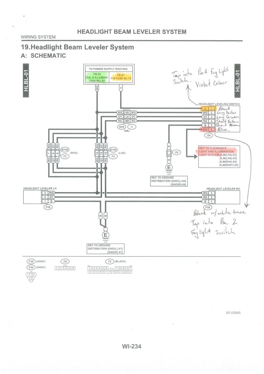
WI-234 (Complete schematic for the wiring of the levelling system)
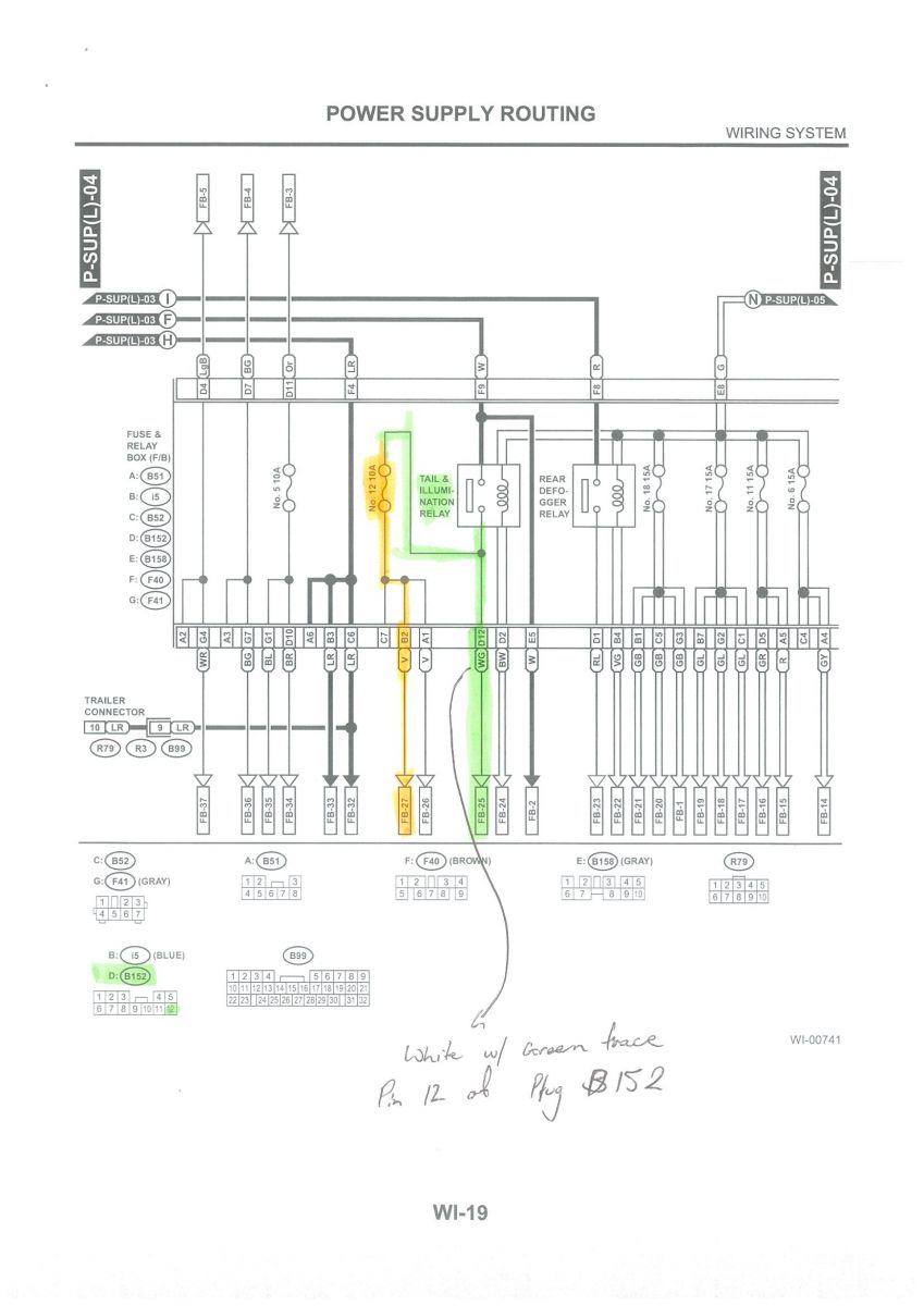
WI-19 (Power Supply Routing schematic showing Tail & Illumination relay and fuse No. 12 10A)
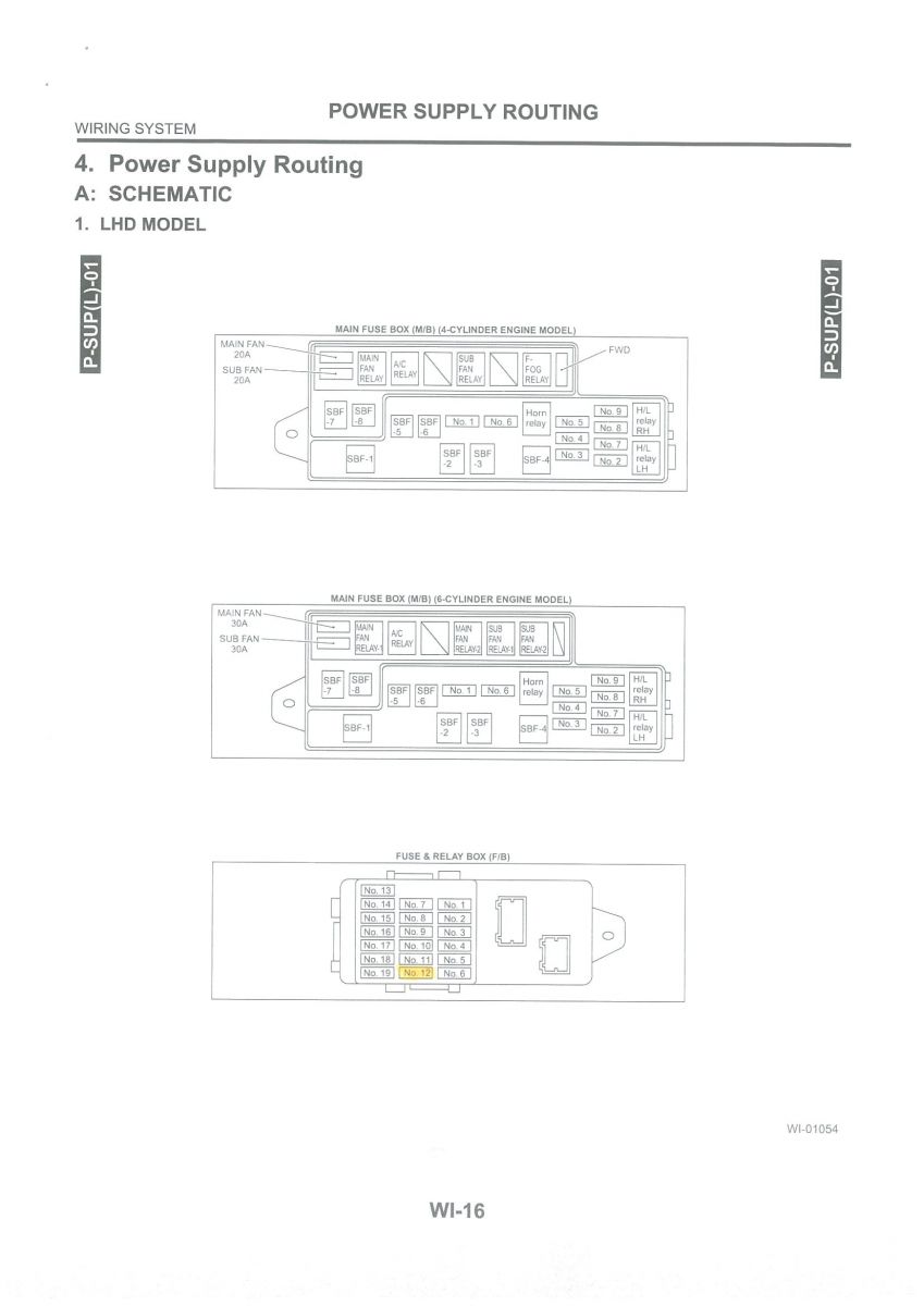
WI-16 (Power Supply Routing showing location of Fuse No. 12 in the Fuse & Relay Box (F/B)
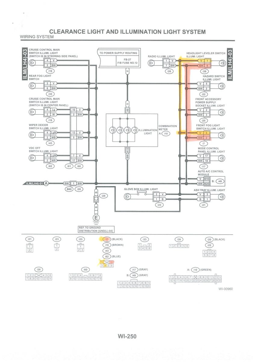
WI-250 (Clearance Light and Illumination Light System showing the leveller switch light that comes on when you turn the headlights on)
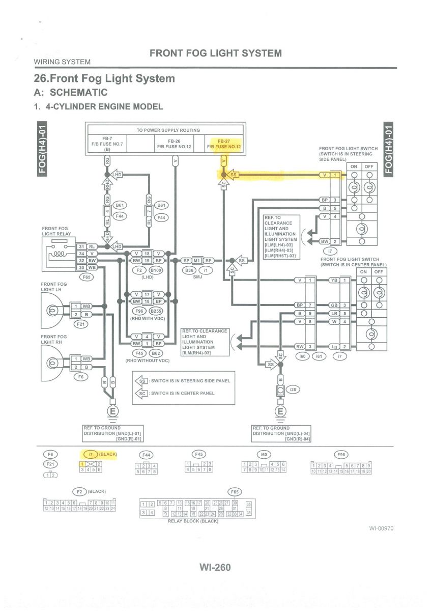
WI-260 (Front fog light system)
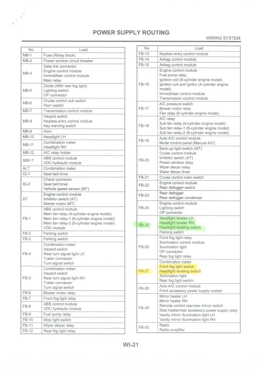
WI-21 (Power Supply Routing, showing a list of some of the fuses and what those fuses supply power to – You want to be playing with circuits FB-25 and FB-27)
Bear in mind, these pages listed are for a LHD 4cyl model. If you have a 6cyl model or an outback, these pages will not line up, and you will need to figure out which pages you need to look at.
A Narva "add-a-circuit" connector for mini-blade fuses (this is a small item that plugs into the spot for a blade fuse, that has an extra wire coming out of it, with space for 2 fuses - one fuse will put power back to whatever circuit you pulled the fuse on to insert this device, and the other fuse give power to the extra wire). Narva part number 54408BL
And lastly, you will need the cabin control switch and the connectors to go on your cabin switch (a small 6 pin plug) and headlight levelling gear (a small 3 wire triangular plug, 1 on the back of each light)
I didn’t have the 6 pin plug for the in-cabin switch, so I had to make my own out of computer connectors - you know the small ones you use to plug the items from the computer case into the motherboard like power switch, reset switch, speaker, power LED, HDD LED, etc. I used them (albeit with some butchering to make them fit) to take the place of that plug, as you cant buy them from Subaru, and import monster didn’t have any in the electrical sections of yahoo auctions.
Ok. Now you have assembled all that stuff, here we go.
First up, mark up your drawings. I used 3 colours – Green, Orange and Pink.
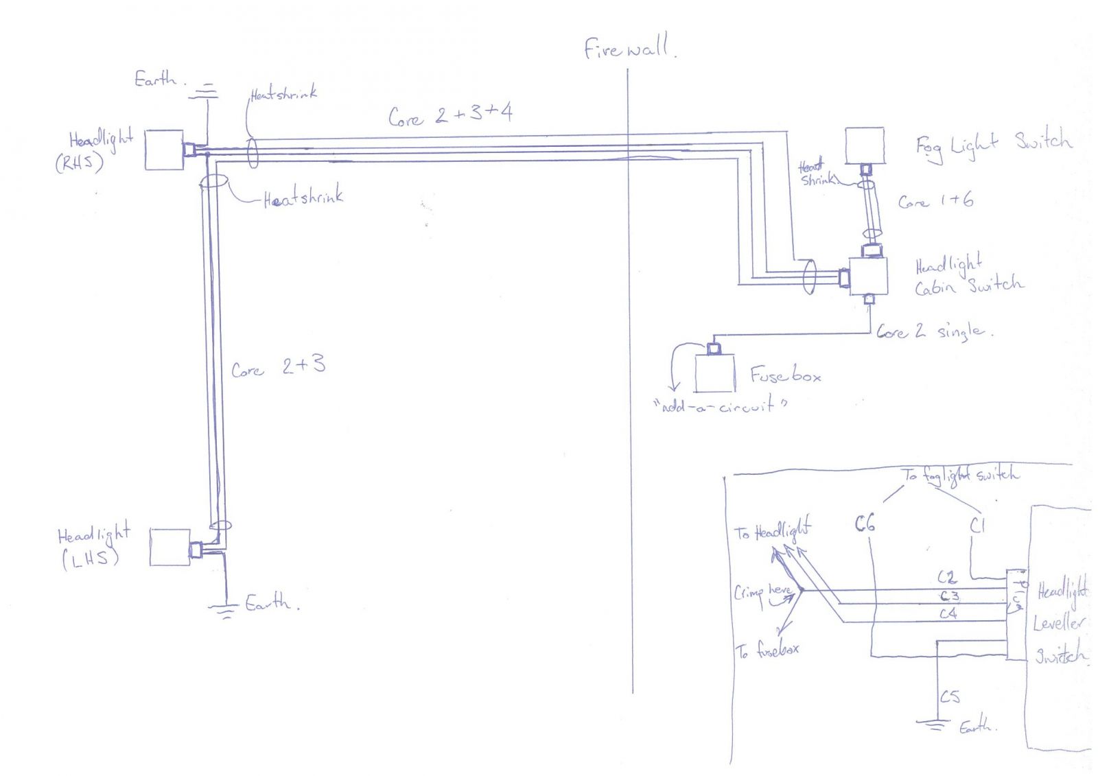
For ease of me trying to explain it, I will scan and put them up here.
Ok, now you have them, you need to allocate your own colours/numbers to the Subaru ones.
If you have the factory cabin switch, this should be easy. Please ignore my legend in the levelling switch diagram on WI-234, it is what wire colours I had to work with.
V (Violet) substituted with Core No. 1 for me. This is the power to the switch when the headlights are on so you can see the switch in the dark. Instead of taking this from the fuse, I tapped into the front fog light switch (see WI-234 and WI-250). Each plug layout is shown at the bottom.
WG (White with Green trace) substituted with Core 2. This is permanent 12V to the control switch and the motors inside the head lights.
GY (Green with Yellow trace) substituted with Core 3. This is the reference back to the cabin switch for the level on the LHS light.
RG (Red with Green trace) substituted with Core 4. This is the reference back to the cabin switch for the level on the RHS light.
B (Black) substituted with Core 5 (I used the Green/Yellow earth wire from the control cable for all grounds of this system. I am a sparky by trade, so if I see a green yellow cable, it’s always earth (or ground as its written in the schematics). This wire needs to go to the frame of the car somewhere close.
BW (Black with White trace) substituted Core 6. This is the ground for the Violet wire (My Core 1). Tap into the fog light switch again. It keeps that circuit complete and together if there are issues down the track, and it also mimics the schematics as it should.
Now you have sorted out your cables, its time to cut them to length. Always leave more than you need, so if you think I haven’t said enough length, leave more.
Earths/Grounds – You will need 3 in this system. 1 at each light, and one off the switch – Core 5. I left mine about 150mm for the headlights, and about 500mm for the switch.
Core 1 (Violet) needs to reach the back of the fog light switch with a bit of slack. My levelling switch was on the LHS of the steering column, so mine needed to be about 500mm long. Yours will be shorter if you put it on the RHS with the fog light switch.
Core 2 (White/Green trace) needs to reach from the switch in the cabin, through the firewall to the RHS headlight, then run from there across the radiator to the LHS headlight. To run it neatly, measure it up and leave an extra 300mm. If you are making looms, make one length for the switch to RHS headlight, cut it, and then make another length to go between the lights.
This wire needs an additional length put from the switch to the fuse box in the kick panel above the accelerator pedal. This will attach to the Narva “add-a-circuit”.
Core 3 (Green/Yellow trace) needs to go from the switch to the LHS headlight. To make life easier, make it the same overall length as Core 2 (all the way from switch to LHS light). I will explain the reason for this later.
Core 4 (Red/Green trace) needs to go from the switch to the RHS headlight.
Core 6 needs to be the same length as Core 1.
Now its time for the heat shrink, spiral wrap etc - whatever you are going to use to make the individual cables up into looms.
Core 6 and 1 need to be wrapped together.
Core 5 stays separate.
The short loop of Core 2 that goes to the fuse box needs to be separate.
From the switch, Core 2 needs to go with Core 3 and Core 4 to the point of the RHS headlight.
The wrap/heat shrink stops there.
Core 4 stops here, and this section of Core 2 stops here also. The second section of Core 2 needs to join to the first section.
Core 3 continues with the second section of Core 2 to the LHS headlight. Wrap this section.
You should end up with a loom that looks like this:
Now that you have a complete loom, you need to run it into the car. You hopefully have some understanding of what part of the loom goes where being you have made it from scratch, so I won’t explain where it should go.
Once it has been run in, trim everything back so you have about 150mm excess at each point. If you have used numbered cores like I have, make sure you leave the numbers exposed at each end so you know which wire goes to which part of the plugs. Then crimp all the Subaru connectors to your new loom:
The 6 pin plug for the switch goes to the respective cores – 1 to 6.
Don’t forget to put the Core 2 double up here – one heading towards the headlight, the other towards the fuse box.
The LHS headlight plug – Core 2, 3 and an earth.
The RHS headlight plug – Core 2, 4 and an earth. Don’t forget the Core 2 double up here as well – one heading for the switch, the other towards the LHS headlight.
Also, crimp the “add-a-circuit” wire to the fuse box length of Core 2.
Ok, with that done, you need to start connecting things.
Earths first people. It doesn’t really matter when you are talking 12V, but it does help if you don’t muck up your clean earths by arcing out your wiring to them. Fit them first.
Put a ring crimp onto the ends of each earth cable.
For the headlights:
I undid the closest bolt to the headlight that holds the front guard on, and slipped a 10mm ring crimp lug in between the guard and the chassis, then did up the bolt again.
For the switch:
I used the same ring crimp, but found something bolted to the steel bar the dash bolts to, undid it, slipped my ring crimp in, and bolted it back up again.
With the earths hooked up, you need to connect the rest of the plugs.
Plug in each headlight plug into the levelling gear.
Plug in the in cabin switch.
Main power for the whole system is supposed to come directly off the Tail & Illumination Relay in the Fuse box in the cabin. If you know where it is, you can tap into a White/Green trace wire that goes into Plug B152, the terminal number is 12. Refer WI-19, highlighted green on my schematics.
Or, you can do what I did, and unplug fuse No.12 (10A) [Location refer WI-16], and plug in the “add-a-circuit” to that fuse holder. You will need to check that you have gotten the “add-a-circuit” around the right way – if the levelling works with no fuses in it, you need to flip it around. Once you have checked this, you can insert the fuses. 10A in where the original circuit went, and 10A into the new circuit.
Walla, you now have a working levelling system!