
Hey guys,
Long story short, I have been planning/wishing/hoping that one day, I could jam an EZ30 into my gen 3. There are a lot of easier, already done, and probably more financially viable options (gen 4 Spec.B H6, H6 Outhouse etc etc) but none were really what I wanted. Wagons don't appeal to me, and I'm fond of the way the gen 3 is. That, or mentally disabled. Either way..
So, after being told to do it by about 100 or so people, my dad and I decided that, after some research here and there, we could do it.
After a little while, we acquired the required (  ) EZ30D from a wrecked Outback.
 22 - 1ZLhedq.jpg 143.61KB
7 downloads
22 - 1ZLhedq.jpg 143.61KB
7 downloads
We put the engine on the engine stand and did an inspection. Despite some average looking oil (bit dark but nothing else), the clearances on the engine and timing hardware looked good.
Time to drop the boring EJ251 and 4EAT combo out.
14 - Ipm6Gti.jpg 175.34KB
5 downloads
Gettin' ready for it.
12 - Gcbz4U0.jpg 122.56KB
6 downloads
Ew.
11 - NCG3a1i.jpg 191.22KB
5 downloads
Yay!
17 - tz28UEq.jpg 232.88KB
5 downloads
All nice and clean now!
9 - 9hdZURk.jpg 238.92KB
5 downloads
7 - wrrnRXl.jpg 327.52KB
4 downloads
Next up, we had to start getting wiring. At this stage, I had little to no experience with physical Subaru communications systems. So naturally, we took the primary bulkhead harness with the dash harness, engine harness, and the last one we got was the front main harness, which is for the fans, lights, and ABS system as well as fusing.
After that, I got the transmission stuff from a friend. The box is a 5MT Dual Range. Standard transmission conversion kit with the stuff and like.
So the total list of parts looks like this:
- EZ30D with all accessories
- 5MT conversion kit (gearbox, shafts, clutch + fly, primary and slave cylinders with lines, clutch and brake peddle, rear diff and crossmembers)
- Full 02 Outback H6 wiring harness (dash loom, bulkhead loom, engine loom and front loom)
- ECU with matching Immobiliser and key transponder (MUST ALL BE MATCHED)
- BFM H6 cluster (attached images of pre-done cluster and expectations)
- Manual interior trim (only one piece has to be changed, lol)
- Outback ABS Pump and module to match harness
- H6 radiator and lines
- H6 fans (these are SLIMMER and more powerful fans than the EJ25 ones, which will not fit with the EZ30 installed)
...and to contrast how big of a job this is, I've probably forgotten a fair bit. I honestly don't know if it would even be easier to keep the auto, lol.
EDIT:
I decided to finally begin with small tid-bits of information and such to try and help those of you after info.
I'll start with..
THE GUIDE TO THE END OF YOUR LIFE (OR AN ENGINE CONVERSION)
Part 1. Fittin' stuff.
1a. Mounting.
So, first things first. Let's get it clear that, mechanically, this is easy. The EZ30 uses the same engine mounts as the EJ engines, make a swap fairly simply. One thing I've noticed is often missed, is that the Outback chassis uses 25x40mm steel bars bolted to the chassis rails to make the k-frame sit lower due to the EZ's bulk. These use the same bolts that hold the k-frame to the chassis, but are longer from the Outback to accommodate.
With the spacers in:
1 - YhMWn65.jpg 158.01KB
4 downloads
And without:
2 - NyU7fxA.jpg 128.24KB
3 downloads
1b. Gearboxes.
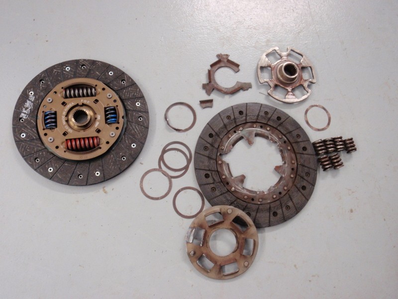
If it fits on an EJ, it fits on the EZ. End o' story. Same said with flywheels and clutches.
IMG_1546.JPG 156.74KB
3 downloads
trans fitted.JPG 154.14KB
3 downloads
Part 2. Differences between the Liberty 2.5 and the 3.0
Firstly, we'll look at the primary differences between the engines. The EJ251 and EZ30D don't really share anything other than, they are both boxers and they both have a cast intake (and even THAT is difference on the EZ). The EZ uses a variable geometry intake (only applicable to 1st gen EZ) which the ECU is trained to take advantage of using low and high RPM modes. The changeover occurs around 3,500RPM-3,750RPM. The EZ also has a 24 valve, quad-cam, chain-driven valvetrain as opposed to the EJ251's 16 valve twin-cam, belt driven valvetrain. Other small differences include top-feed injectors on the EZ as opposed to the EJ25's side-feed injectors. The EJ25 also uses a coil pack with leads as opposed to the EZ using a coil-over-spark config.
Part 3. The nightmare. Okay, it's not THAT bad but it is wiring. (Not needed for H6 AT swaps)
The main bulkhead
Not much to be said here, really. This is the main piece of wiring that will have to be swapped.
IMG_1555.JPG 134.99KB
3 downloads
the loom.JPG 116.95KB
3 downloads
The inhibitor harness
Ironically, there's one main piece of wiring primarily responsible for making sure the car can run, and that's a small loom that you'll find connected to the shifter module on the side of the auto gearbox. This is called the inhibitor harness. I'm not going to screw around trying to explain it, just do this. People call the plug you'll be referencing plug "T3" but it has "B2" printed on the side. The layout can be found in the A/T Control System for the 6-cylinder engine with/without VDC (I used page WI-53).
So, bridge wires found on pins 1 and 4, following the pin out on the service manual section I've attached. This will make the car start.
(remind me to check the power wire for the VSS - it has 5 volts)
That's pretty much it.
The VSS for manual transmissions and gauge cluster wiring for it
The VSS is a small thingy attached the side of the 5MT Subaru gearbox. It has three pins, signal, power (+5Vdc) and ground. The ground can be attached to the nearest bolt, whereas the power has to be attached to a wire on the inhibitor harness (due to edit). The signal, I personally recommend, should be run directly up through the firewall and connected to the cluster.
When I say that, you're probably thinking "Well Tim, that's just dandy. WHERE?! THE INTERNET SAID PIN 13 ON CONNECTOR i10 AND IT'S WRONG.  " That's because that is exactly what happened to me because I was following a USDM forum and they have different looms. Easy enough. On that page we were referencing for the inhibitor harness, it shows a connector called "A: i10 (GREEN)". This is a gauge cluster connector on the pretty new wiring you've painfully installed. Pin 11 (eleven) on connector i10 (or as I eloquently called it, "the big c**t") is used for the VSS on an MT vehicle.
And that should do it!
That's a purdy lookin' cluster..
The transmission control unit
Chuck it out.
That ends the guide for now! If there's any questions, please post or message and I'll try to help!
After all that, let's look at where the project is at the moment. Please let me know if the images aren't working and I'll fix it up. Images embedded now.
Yes, I have to go through and add descriptions everywhere haha.
Odds are, I'll add to this post a lot and hopefully answer any of your questions! thanks yo!
And some extra pics for your perusal. I've gone through and added a couple.
5 - XumQBbG.jpg 147.13KB
3 downloads
IMG_2119.JPG 163.41KB
3 downloads
IMG_1554.JPG 100.11KB
3 downloads
Attached Files
-
dash.JPG 99.64KB
3 downloads